Determination and control of wellbore fluid level, output flow, and desired pump operating speed, using a control system for a centrifugal pump disposed within the wellbore

a control system and centrifugal pump technology, applied in the field of pumping systems, can solve the problems of sensor or sensor placement being inconvenient or difficult to access, sensor(s) being exposed to a harmful environment, sensors adding to initial system cost and maintenance cost, etc., to enhance the market appeal of the apparatus, reduce the cost of maintenance, and reduce the effect of sensor placemen

Inactive Publication Date: 2010-02-23
UNICO LLC
View PDF112 Cites 61 Cited by
  • Summary
  • Abstract
  • Description
  • Claims
  • Application Information

AI Technical Summary

Benefits of technology

[0019]The disadvantages and limitations of the background art discussed above are overcome by the present invention. With this invention, there is provided a method of continuously determining operational parameters of a down hole pump used in oil, water or gas production. In one embodiment, wherein the pump is a centrifugal pump, the pump is rotationally driven by an AC electrical drive motor having a rotor coupled to the pump for rotating the pump element. In deep wells, it is common practice to use an AC electrical drive motor designed to operate at voltages that are several times that of conventional industrial motors. This allows the motors to operate at lower currents, thereby reducing losses in the cable leading from the surface to the motor. In those cases, a step up transformer can be used at the surface to boost the typical drive output voltages to those required by the motor.
[0023]The operation of a centrifugal pump is controlled to enable the pump to operate periodically, such that the pump can achieve a broad average flow range while maintaining high efficiency. This obviates the need to replace a centrifugal pump with another pump, such as a rod beam pump, when fluid level or flow in the well decreases over time. In accordance with another aspect of the invention, a check valve is used to prevent back flow during intervals in which the pump is turned off.
[0024]In accordance with a further aspect of the invention, an optimizing technique is used in the production of methane gas wherein it is necessary to pump water off an underground formation to release the gas. The optimizing technique allows the fluid level in the well to be maintained near an optimum level in the well and to maintain the fluid at the optimum level over time by controlling pump speed to raise or lower the fluid level as needed to maintain the maximum gas production.
[0039]Calculation of a flow rate from a centrifugal pump, as a function of the selected speed and a fluid level in a wellbore, may further include a preliminary step of determining the fluid level in the wellbore, according the methods of the present invention. This aspect of the invention provides particular advantage in applications where electrically driven submersible pumps exhibit only very small changes in pump power or torque as the flow changes through the pump, or in systems having pumps with pump curves that are not strictly monotonic, with a maximum occurring near the pump Best Efficiency Point (BEP). In such pumps, determination of pump flow, using only input speed and torque in the manner described herein with regard to other aspects of the invention, can be difficult. By determining the flow rate of the centrifugal pump as a function of a selected pump speed and the fluid level in the wellbore, the flow rate may be determined, according to the invention, without the need for having a flow sensor for directly measuring the flow, thereby reducing complexity and improving reliability through practice of the invention.
[0043]The invention also provides an improved apparatus and method for detecting and dealing with a pump-off or gas-lock condition in a wellbore. The invention also provides an apparatus and method for periodic determination of a minimum fluid depth and / or maximum pump speed at which the well may be operated continuously without encountering a pump-off or gas-lock condition. The invention further provides a method and apparatus for controlling the well in a manner allowing pumping at a maximum sustainable rate, while precluding the possibility of encountering a pump-off or gas-lock condition, during either normal continuous operation of the well or recovery from a pump-off or gas-lock condition. The invention also provides an apparatus and method for automatically periodically adjusting the pump speed, if necessary, to maintain a maximum pumping rate from the well.
[0044]The invention may be utilized for detecting the onset of a pump-off and / or gas-lock condition by monitoring an appropriate parameter, such as pump input torque or current to an electric motor driving the pump, or a derivative or other computed value as a function of the monitored parameter. In one form of the invention, the onset of a pump-off and / or gas-lock condition is detected when motor current or torque drops below an under load value. Unlike prior systems and methods, however, which required that the pump be shut down following detection of a pump-off and / or gas-lock condition, the invention allows the pump to be controlled in such a manner that it can continue to operate at a reduced speed, during the period of time that the well is recovering from the pump-off and / or gas-lock condition.

Problems solved by technology

In many applications, the placement required for the sensor or sensors is inconvenient or difficult to access and may require that the sensor(s) be exposed to a harmful environment.
Also, sensors add to initial system cost and maintenance cost as well as decreasing the overall reliability of the system.
Centrifugal pumping systems are inherently nonlinear.
This presents several difficulties in utilizing traditional closed-loop control algorithms, which respond only to error between the parameter value desired and the parameter value measured.
Also, due to the nature of some sensors, the indication of the measured parameter suffers from a time delay, due to averaging or the like.
Consequently, the non-linearity of the system response and the time lag induced by the measured values makes tuning the control loops very difficult without introducing system instability.
If the fluid level in the well drops too low, undesirable conditions known as “pump-off,” or “gas-lock,” may occur in the pump.
Unfortunately, in the past, wellbore pumping systems and controls did not provide a convenient apparatus or method for determining what the maximum pump speed should be, during recovery, in order to preclude triggering a subsequent pump-off and / or gas-lock condition.
During the time that the pump is shut down for recovery, no revenue is being generated by the well.
In addition, the uncertainty, in the past, with regard to avoiding a pump-off or gas-lock condition, and the time and procedure involved for recovering from such conditions, has led to undesirable wear and tear on the pumping equipment, as well.
These down-hole sensors are expensive and suffer very high failure rates, necessitating frequent removal of the pump and connected piping to facilitate repairs.
Likewise, the need for surface flow sensors adds cost to the pump system.
Also, centrifugal pumps are inefficient when operating at slow speeds and / or flows, wasting electrical power.

Method used


Image

  • Determination and control of wellbore fluid level, output flow, and desired pump operating speed, using a control system for a centrifugal pump disposed within the wellbore
  • Determination and control of wellbore fluid level, output flow, and desired pump operating speed, using a control system for a centrifugal pump disposed within the wellbore
  • Determination and control of wellbore fluid level, output flow, and desired pump operating speed, using a control system for a centrifugal pump disposed within the wellbore

Examples


Embodiment Construction

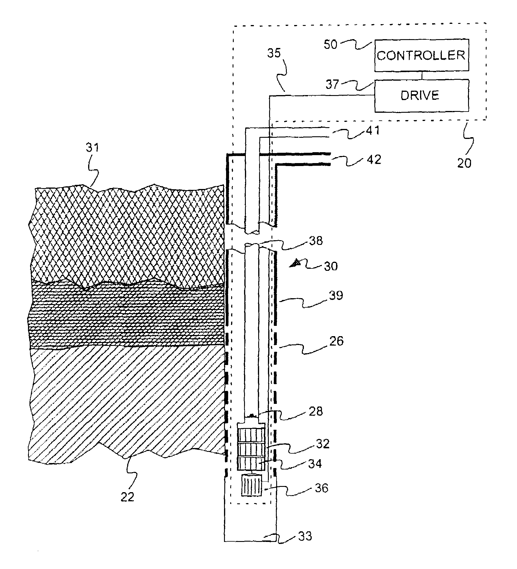
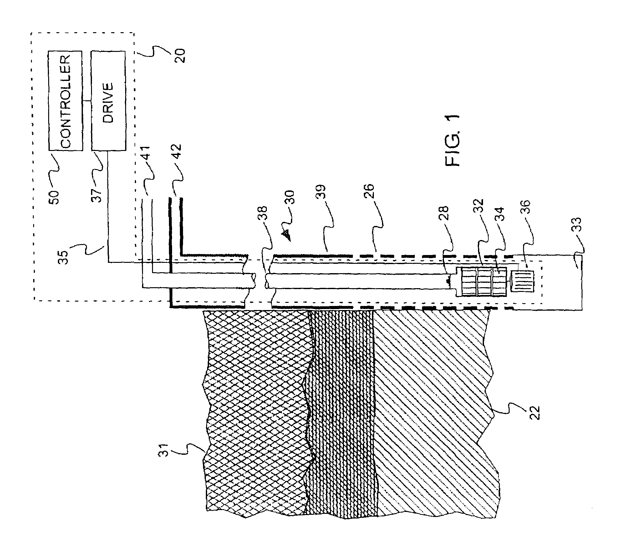
[0077]Referring to FIG. 1, the present invention is described with reference to an oil well 30 wherein oil is to be pumped from an underground formation 22. The well includes an outer casing 39 and an inner tube 38 that extend from ground level to as much as 1000 feet or more below ground level. The casing 39 has perforations 26 to allow the fluid in the underground formation to enter the wellbore. It is to be understood that water and gas can be combined with oil and the pump can be used for other liquids. The control apparatus can also be used for pumping water only. The bottom of the tube generally terminates below the underground formations.

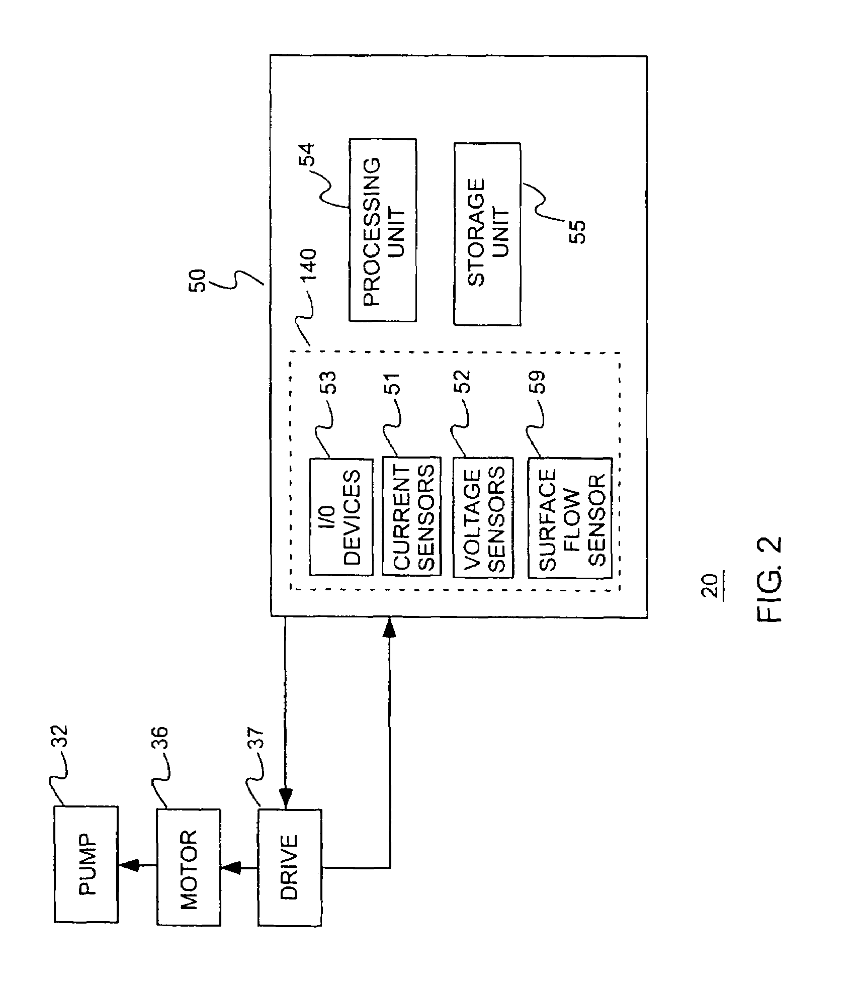
[0078]A centrifugal pump of the type known as an electric submersible pump (ESP) 32 is mounted at the lower end of the tube 38 and includes one or more centrifugal pump members 34 mounted inside a pump housing. The pump members are coupled to and driven by a drive motor 36 which is mounted at the lower end of the pump housing. The tube 38 has...


PUM

PropertyMeasurementUnit
lengthaaaaaaaaaa
lengthaaaaaaaaaa
lengthaaaaaaaaaa

Abstract

A method and apparatus for determining a fluid level and / or output flow during operation of a centrifugal pump, are provided, which may be used for production of gas and / or oil from a well, and include a vector feedback model to derive values of torque and speed from signals indicative of instantaneous current and voltage drawn by the pump motor, a pump model which derives values of the fluid flow rate and the head pressure for the pump from torque and speed inputs, a pumping system model that derives, from the estimated values of the pump operating parameters, an estimated value of fluid level and other pumping system parameters. Controllers responsive to the estimated values of the pumping system parameters control the pump to maintain fluid level at the pump input, near an optimum level, or within a safe operating range and / or output flow from the pump.

Description

CROSS-REFERENCE TO RELATED PATENT APPLICATIONS[0001]This application claims the benefit of U.S. Provisional Application No. 60 / 796,230, which was filed on Apr. 28, 2006. This application is a continuation-in-part of U.S. patent application Ser. No. 11 / 502,677 entitled “Control System for Centrifugal Pumps”, which is a divisional of published U.S. Patent Application No. US 2004 / 0064292, which was filed on Sep. 5, 2003 and issued as U.S. Pat. No. 7,117,120 on Oct. 3, 2006. The aforementioned U.S. patent Divisional application Ser. No. 11 / 502,677, entitled “Control System for Centrifugal Pumps,” claims the benefit of and / or priority to: U.S. Provisional Application No. 60 / 429,158 entitled “Sensorless Control System for Progressive Cavity and Electric Submersible Pumps”, which was filed on Nov. 26, 2002; U.S. Provisional Application No. 60 / 414,197 entitled “Rod Pump Control System Including Parameter Estimator”, which was filed on Sep. 27, 2002; published U.S. Patent Application No. US ...

Claims


Application Information

Patent Timeline
Patent Type & Authority Patents(United States)
IPC IPC(8): G06F11/30G01F15/00G05D9/00
CPCE21B47/042G01F1/78G01F1/80G01F23/00F04D15/0088G05B17/02G05D9/12F04D15/0066G01F23/22F04D13/10F04D9/001E21B47/047
Inventor ANDERSON, ROBB G.BECK, THOMAS L.
Owner UNICO LLC
Why Eureka
Try Eureka