Spring-Loaded Split-Tongue Connector System

Active Publication Date: 2015-06-25
ENGINEERED FLOORS LLC
View PDF13 Cites 32 Cited by
  • Summary
  • Abstract
  • Description
  • Claims
  • Application Information

AI Technical Summary

Benefits of technology

[0013]The objective of the present invention is to provide a versatile, robust, low cost connector system, suitable for the mechanical joining of two construction elements; having a mating groove geometry that can be formed at a rate required for economical production of vinyl, laminate, or hardwood flooring; and that is also suitable for a wide variety of other less demanding applications, e.g., ready-to-assemble furniture.
[0014]The invention comes in two preferred embodiments: a lateral embodiment and a normal embodiment. The advantage of the lateral embodiment relative to the normal embodiment is that, once assembled, the lateral embodiment is completely hidden from view; a feature that is very desirable for ready-to-assemble furniture. Conversely, the normal connector, though visible after assembly, is only visible from the under surface of flooring, its preferred application, and hence, is totally hidden from view by the upper decorative flooring surface. In addition, in a completed floor installation, the normal

Problems solved by technology

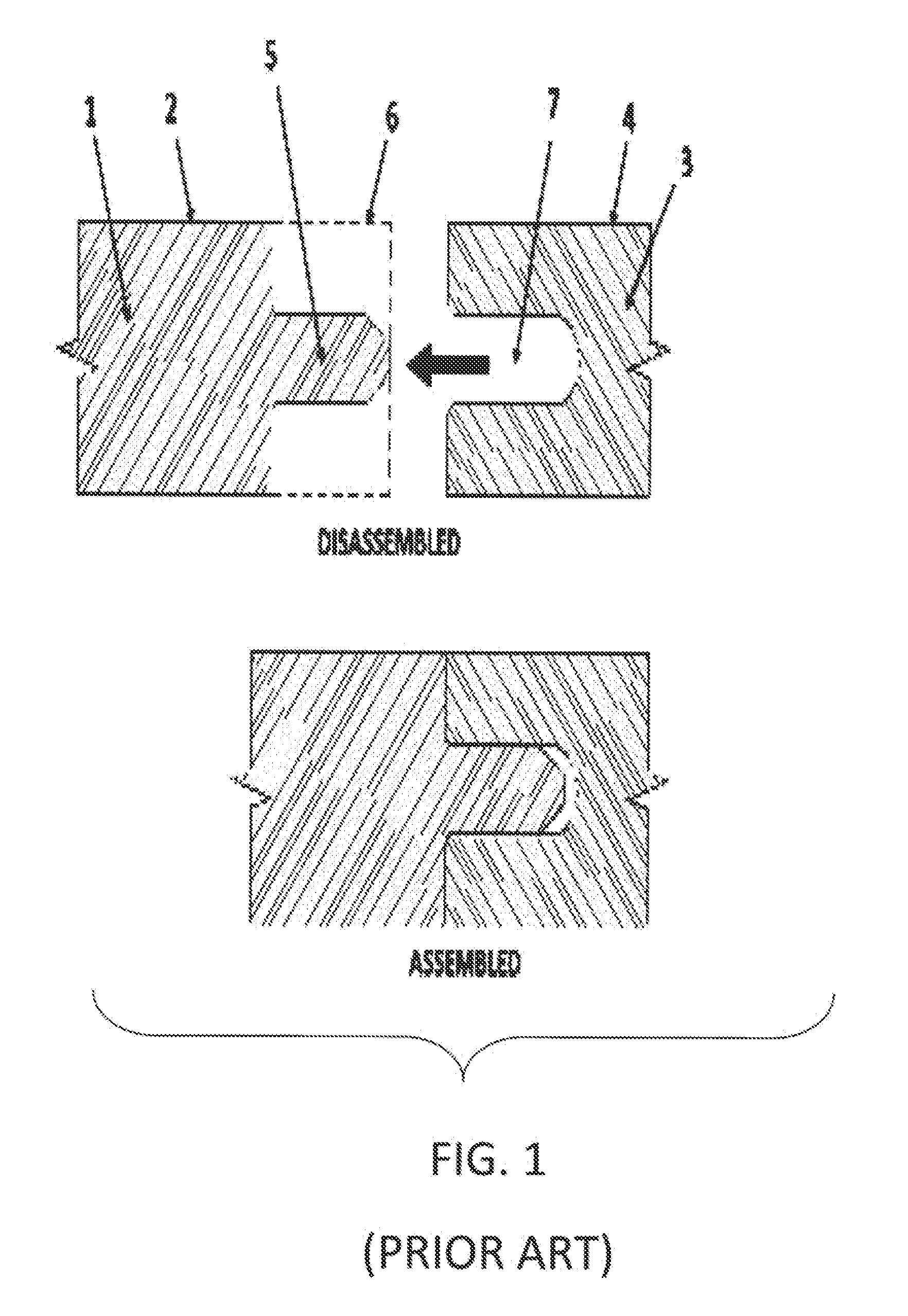
A solid tongue 5 is machined from the solid substrate materi

Method used


Image

  • Spring-Loaded Split-Tongue Connector System
  • Spring-Loaded Split-Tongue Connector System
  • Spring-Loaded Split-Tongue Connector System

Examples


Embodiment Construction

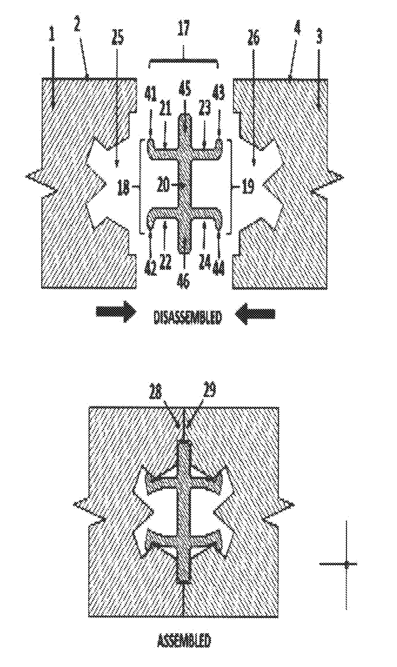
[0040]The connector system disclosed herein has two major preferred embodiments: a lateral connector system embodiment shown schematically in FIG. 4 and a normal connector system embodiment shown schematically in FIG. 5.

[0041]The following specification is divided into four sections. The first section, comprising FIGS. 4 and 5 focuses on the structure and fabrication of the connector element of the preferred embodiments (item 17 in FIG. 4 and item 31 in FIG. 5). The second section focuses on the structure and fabrication of the connector mating groove of the preferred embodiments and comprises FIGS. 6, 7, and 8. The third section focuses the manner in which the connector element and the mating groove of the preferred embodiments mechanically interact and comprises FIGS. 9 to 18. The fourth and last section focuses on an alternative connector and groove embodiment and comprises FIGS. 19 to 22.

[0042]FIG. 4 shows the lateral embodiment of the connector system as used to connect hardwoo...


PUM


Abstract

A connector system for mechanically connecting two structural elements to each other, consisting of a connector element and mating grooves in each structural element. The connector element is comprised of a base plate having a split-tongue element at each side or end of said base plate. Each joined element has a mating groove formed into its connector-receiving surface. The mating groove is designed to allow fabrication via four sequential circular saw cuts, without loss of saleable decorative surface, and at a rate consistent with economical commercial production of vinyl, laminate, or hardwood flooring. The connector element is readily extruded in a variety of polymers, including PVC. The connector and mating grooves interact so as to generate a force component acting to forcibly draw the connector into the mating grooves. The connector system operation is relatively insensitive to geometric deviations associated with normal manufacturing methods.

Description

CROSS-REFERENCE[0001]This is a continuation-in-part application to the U.S. application Ser. No. 13 / 086,424, filed on Apr. 14, 2011, from which priority is claimed, and entirety of which is hereby incorporated by reference.BACKGROUND OF INVENTION[0002]1. Field of Invention[0003]This invention relates to a connector system for mechanically joining building panels (such as vinyl, laminate, or hardwood flooring); mechanically attaching decorative items (such as wall panels, ceiling panels, or automotive trim); mechanically attaching subsystems (such as automotive dashboards); or mechanically connecting elements of ready-to-assemble furniture.[0004]2. Description of Related Art[0005]FIG. 1 is a schematic drawing of the ubiquitous tongue and groove joining system typically used to join structural elements such as hardwood flooring. In the figure, hardwood flooring substrate element 1 with decorative surface 2 is to be connected to hardwood flooring substrate element 3 with decorative sur...

Claims


Application Information

Patent Timeline
IPC IPC(8): F16B5/00E04F13/08A47B96/20E04F15/02
CPCF16B5/002A47B96/201E04F13/0801E04F15/02166E04F13/0894E04F15/02038E04F2201/0115E04F2201/0146E04F2201/042E04F2201/05E04F2201/0517F16B5/006
Inventor BAKER, GEOFFREY ALAN
Owner ENGINEERED FLOORS LLC
Why Eureka
Try Eureka