Fast connector structure for cleaners

Active Publication Date: 2015-06-25
YI JHONG DEV
View PDF0 Cites 4 Cited by
  • Summary
  • Abstract
  • Description
  • Claims
  • Application Information

AI Technical Summary

Benefits of technology

[0010](a) The fast connector structure for cleaners of the present invention utilizes two positioning pieces to block the arc-shaped surface of the recessed ring slot at both inner and outer sides, which provides a full circle stabilization to the water pipe and allows the water pipe to be stably connected to the connector body, thereby preventing the detachment of the connector body from the water pipe due to the force generated by h

Problems solved by technology

These screw bolts have to be precisely aligned to achieve accurate positioning and a poor alignment likely causes a water leak.
However, for the previously invented fast connector structure as above described, the inner side edge 714 of the positioning piece 71 blocks the recessed ring slot 62 at only one side and does not provides a full

Method used


Image

  • Fast connector structure for cleaners
  • Fast connector structure for cleaners
  • Fast connector structure for cleaners

Examples


Example

[0022]Further details of the fast connector structure for cleaners of the present invention, including the technical objective, the structural characteristics, and the advantages of the subject of the present invention will be described as following, with assistance of the drawings.

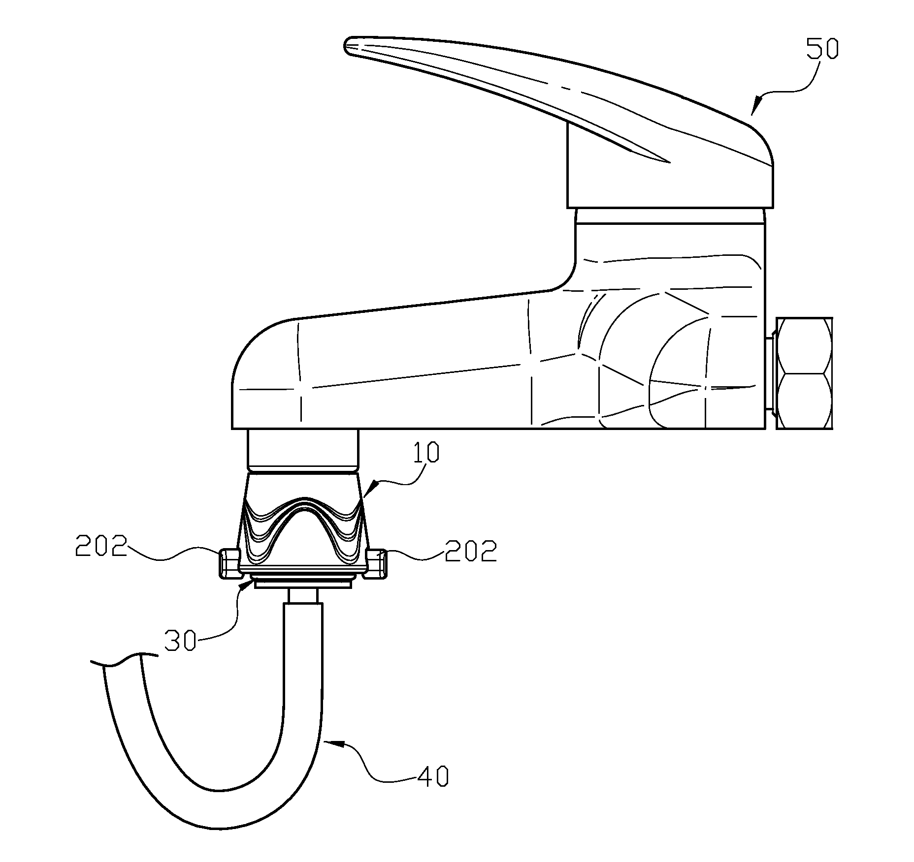
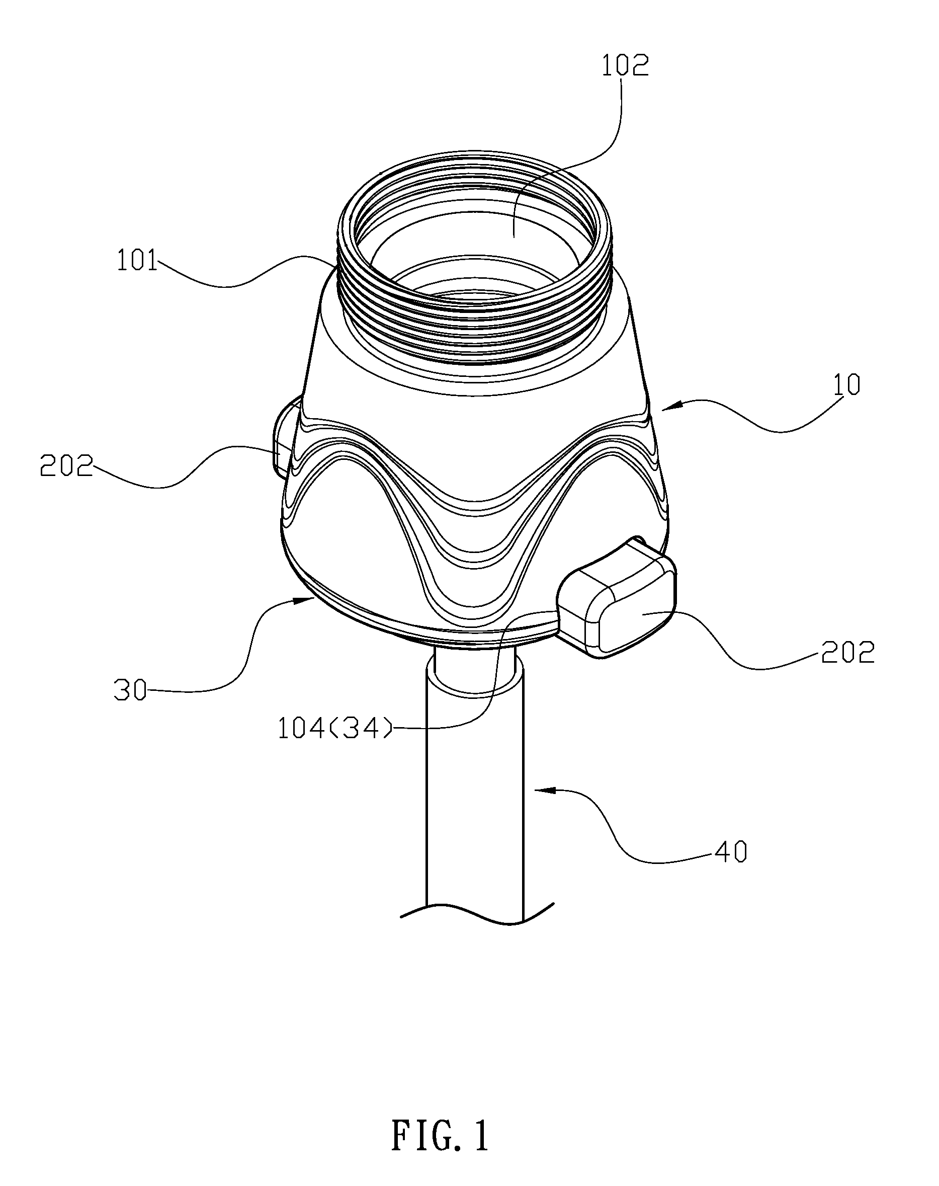
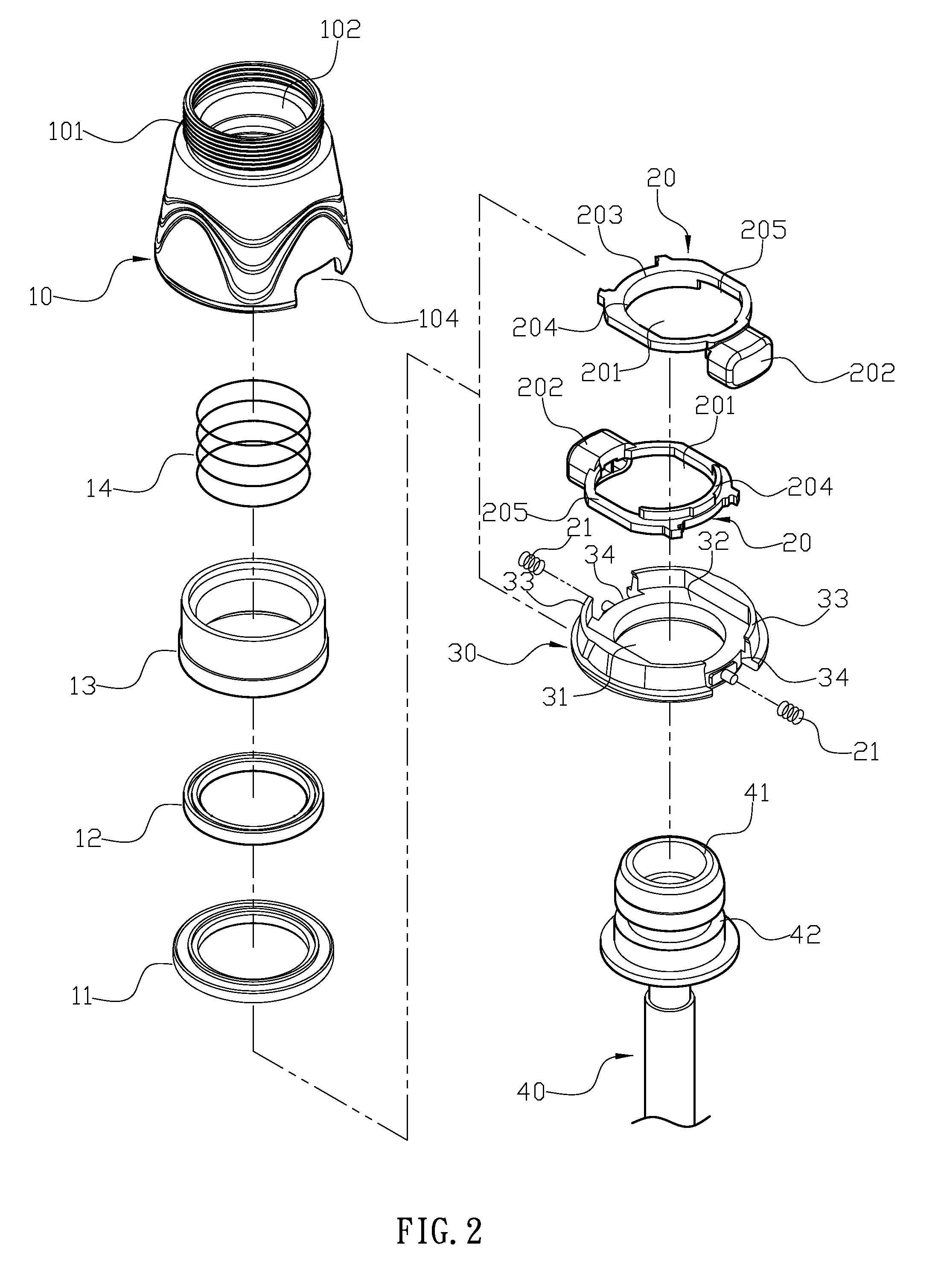
[0023]The fast connector structure for cleaners of the present invention, as illustrated in FIGS. 1 to 5, may include a connector body 10, two positioning pieces 20, a bottom plate 30, and a water pipe 40, wherein one end of the connector body 10 is used for the installation of the water inlet end 41 of the water pipe 40, and the other end is threaded for being installed into the screw hole of the water outlet opening of the faucet 50. The water through hole 102 is located in the center of the connector body 10, and the connector body 10 has a ring cap 11, a bushing liner 13, and a spring 14. The bottom portion of the connector body 10 is expanded and forms a recessed portion 103 that connects to the wate...


PUM


Abstract

A fast connector for cleaners, which comprises: a connector body, two positioning pieces, a bottom plate and an water pipe, wherein the connector body has a water through hole in its center and the bottom portion which is expanded and formed into a recessed portion with two first openings. Two positioning pieces are reversely stacked, each having a through slot in its center, a push button at its outside, and a restored spring placed between the inner side surface of the push button and the second opening of the bottom plate which allows the positioning piece to move laterally and in opposite directions. The bottom plate has a through slot in its center, a trough on both sides of the slot, and two second openings for placing the positioning pieces.

Description

FIELD OF THE INVENTION[0001]The present invention relates to a fast connector structure for cleaners, more particularly to a fast connector structure that employs a ring member for a secured circular positioning.BACKGROUND OF THE INVENTION[0002]A conventional connector structure for cleaners is usually connected to a water faucet with screw bolts, and is pushed to contact the water faucet with the force generated by the screw bolts. These screw bolts have to be precisely aligned to achieve accurate positioning and a poor alignment likely causes a water leak. To solve this problem of the conventional connector structure, the inventor has previously invented a fast connector structure for cleaners as illustrated in FIGS. 9 to 11. The fast connector structure of the previous invention comprises a water pipe 60 and a fast connector 70, wherein one end of the fast connector 70 is connected to the water inlet end 61 of the water pipe 60, and the other end of the fast connector 70 is molde...

Claims


Application Information

Patent Timeline
IPC IPC(8): F16L37/14F16L37/48F16L15/00
CPCF16L37/142F16L37/48F16L15/001E03C1/086F16L37/0841
Inventor JUAN, CHUNG-CHUN
Owner YI JHONG DEV
Why Eureka
Try Eureka