

Thermal energy storage system
- Summary
- Abstract
- Description
- Claims
- Application Information
AI Technical Summary
Benefits of technology
Problems solved by technology
Method used
Image

Examples
Embodiment Construction
[0035]The embodiments disclosed below are not intended to be exhaustive or limit the invention to the precise form disclosed in the following detailed description. Rather, the embodiments are chosen and described so that others skilled in the art may utilize their teachings. Further, in the following description, expressions “substantially”, “around”, and “approximately” mean “to within 10%”. Further, only those elements which are necessary to the understanding of the present invention will be described and shown in the drawings. In particular, the structure and the operation of a solar water heater and of a double-flow ventilation are well known by those skilled in the art and are not described in detail.
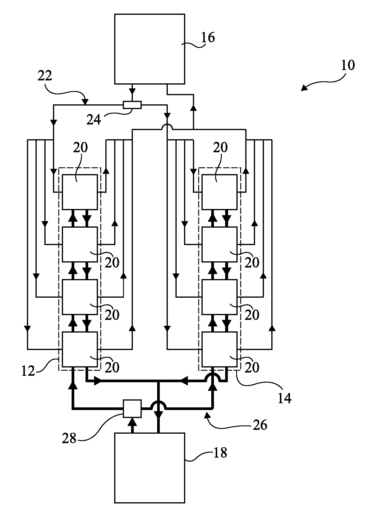
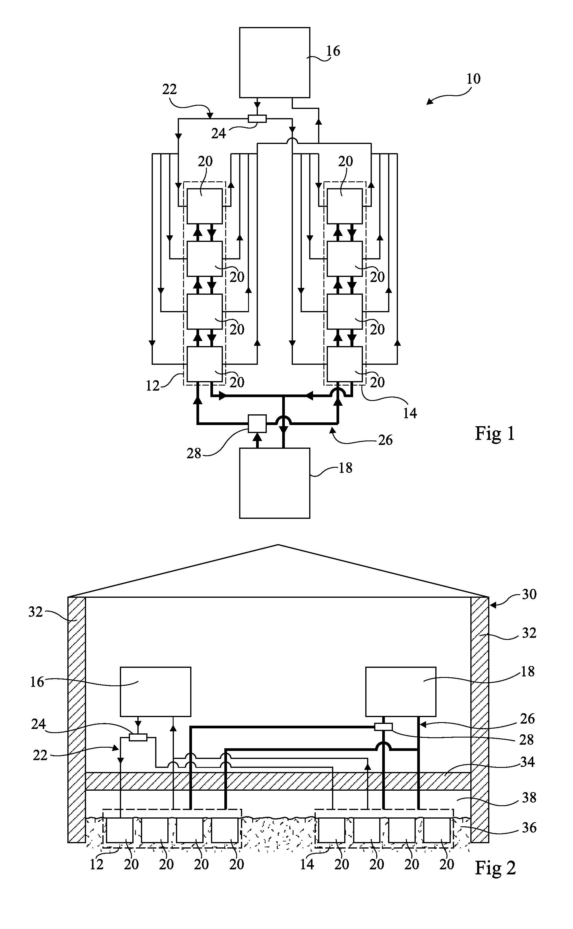
[0036]FIG. 1 partially and schematically shows an embodiment of a heating device 10.
[0037]Heating device 10 comprises two thermal energy accumulators 12, 14, a thermal energy generation device 16 supplying heat accumulators 12, 14, and a device 18 for consuming the thermal energy s...
PUM
 Abstract
Description
Claims
Application Information