

Multiplication Circuit Providing Dynamic Truncation
- Summary
- Abstract
- Description
- Claims
- Application Information
AI Technical Summary
Benefits of technology
Problems solved by technology
Method used
Image

Examples
Embodiment Construction
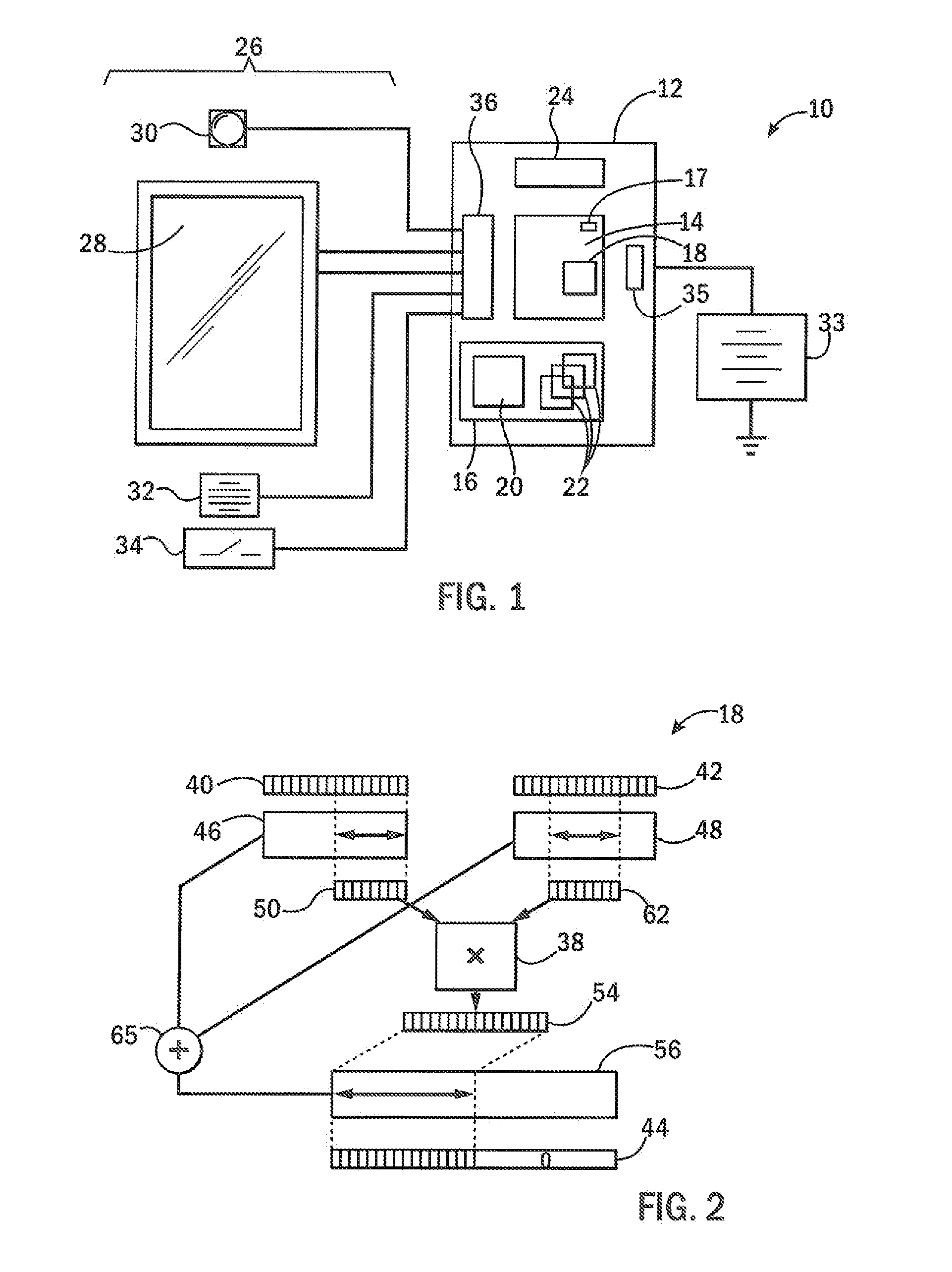
[0036]Referring now to FIG. 1, a portable computational device 10, such as a cell phone may provide a hardware platform 12, for example, contained on a circuit card or the like, composed of inter-communicating circuit elements including a processor 14 and associated memory 16.
[0037]The processor 14 may be a single or multicore processor and may include a hardware multiplier circuit 18 as will be described below either integrated into the processor or as a coprocessor. In one embodiment, the processor 14 or another element of the platform 12 may provide for a temperature sensor 17 as will be discussed below.
[0038]As is generally understood in the art, during operation of the computational device 10, the processor 14 executes programs contained in the memory 16 including, for example, an operating system 20 and multiple application and driver programs 22. The memory may also include data files (not shown) holding data used by the operating system 20 or application and driver programs ...
PUM
 Abstract
Description
Claims
Application Information