

Power supply apparatus and image forming apparatus
a technology of power supply apparatus and image forming apparatus, which is applied in the direction of electric variable regulation, process and machine control, instruments, etc., can solve the problem of lack of balance of two capacitors, and achieve the effect of preventing electromagnetic nois
- Summary
- Abstract
- Description
- Claims
- Application Information
AI Technical Summary
Benefits of technology
Problems solved by technology
Method used
Image

Examples
first embodiment
[0049]Power Supply Apparatus
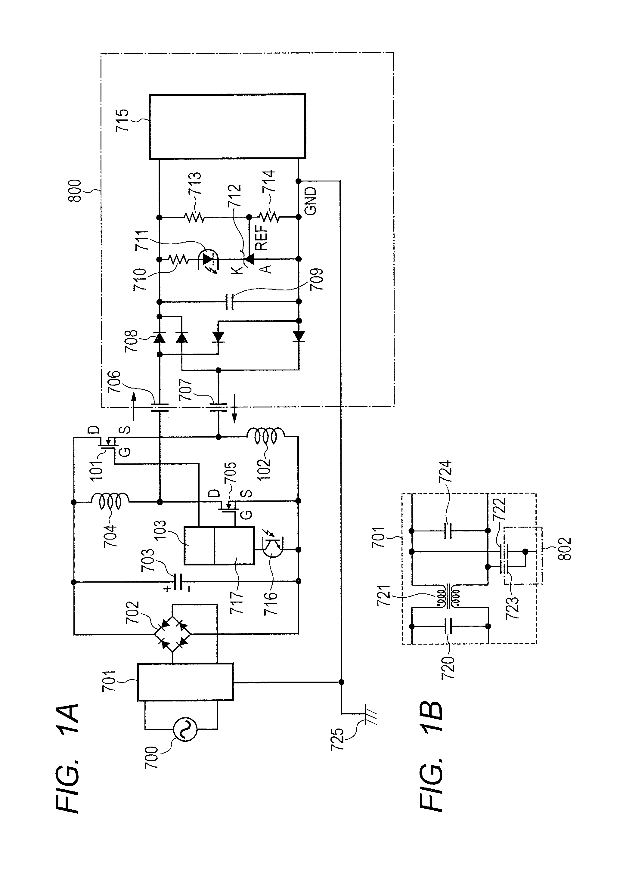
[0050]FIG. 1A and FIG. 1B illustrate a structure of a DC-to-DC converter as a power supply apparatus according to a first embodiment of the present invention. The same reference numerals are used to designate the same members as those in the related art described with reference to FIG. 8A, and description thereof is omitted. The power supply apparatus of this embodiment includes a second switch element 101 (hereinafter simply referred to as switch element 101), a second inductor 102 (hereinafter simply referred to as inductor 102), and a switching control circuit 103. Note that, in this embodiment, a switch element 705 is a first switch element, and an inductor 704 is a first inductor. One end (in this embodiment, a source terminal S) of the switch element 705 is connected to one pole (in this embodiment, a negative pole) of a smoothing capacitor 703, and another end (in this embodiment, a drain terminal D) of the switch element 705 is connected to one en...
second embodiment
[0059]Power Supply Apparatus
[0060]FIG. 3 illustrates a structure of a DC-to-DC converter as a power supply apparatus according to a second embodiment of the present invention. The same reference numerals are used to designate the same members as those in the first embodiment, and description thereof is omitted. The power supply apparatus of this embodiment includes a first switch element 301 (hereinafter simply referred to as switch element 301), a second switch element 303 (hereinafter simply referred to as switch element 303), and an inductor 302. One end (in this embodiment, a drain terminal D) of the switch element 301 is connected to one pole (in this embodiment, a positive pole) of the smoothing capacitor 703. One end (in this embodiment, a source terminal S) of the switch element 303 is connected to another pole (in this embodiment, a negative pole) of the smoothing capacitor 703. The inductor 302 is connected between another end (in this embodiment, a source terminal S) of t...
third embodiment
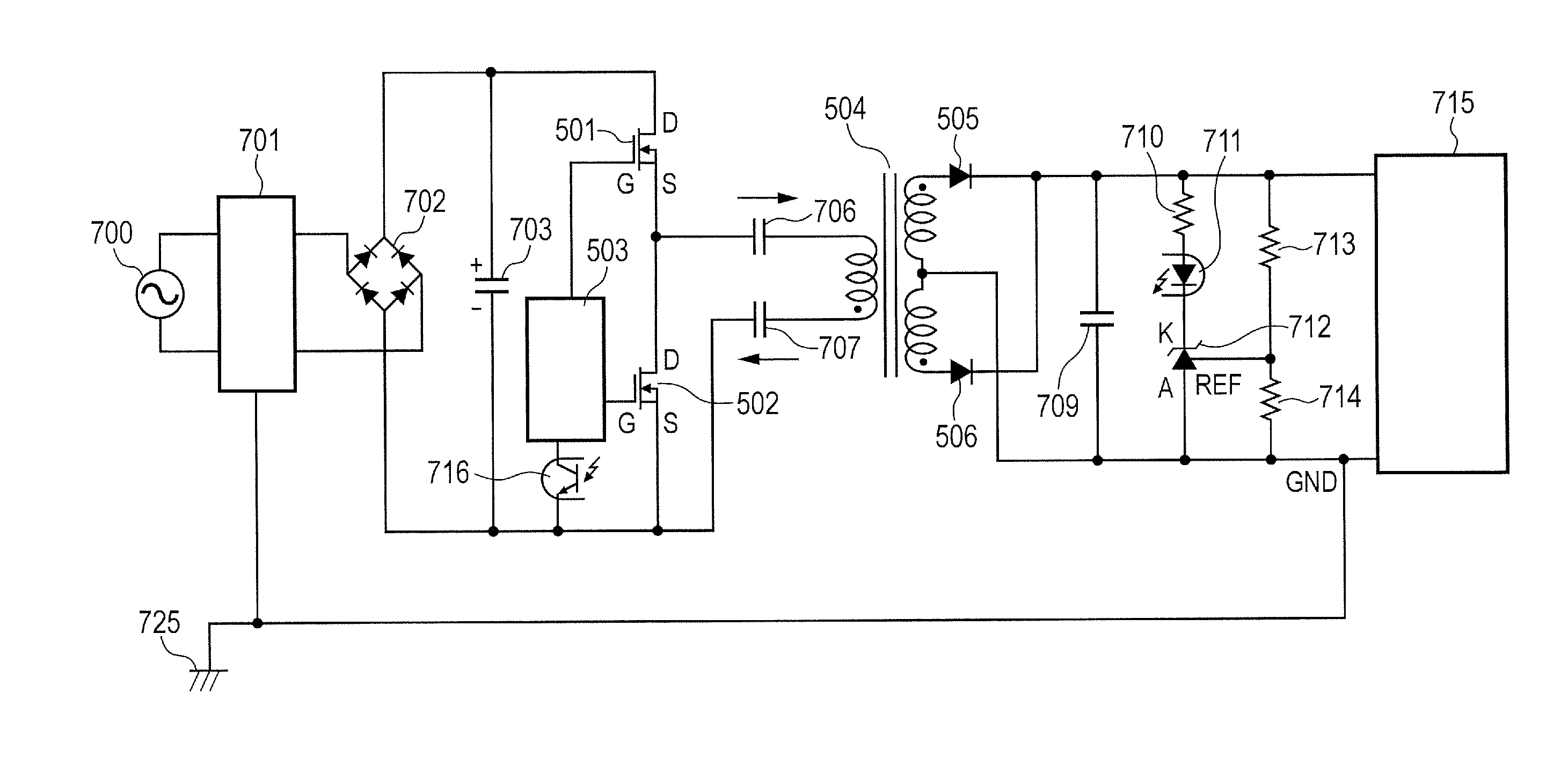
[0068]FIG. 5 illustrates a structure of a DC-to-DC converter as a power supply apparatus according to a third embodiment of the present invention. In the power supply apparatus of this embodiment, the primary side and the secondary side are insulated from each other by a transformer 504. The two capacitors 706 and 707 are configured to also have the insulation function so that an insulation length by the transformer 504 can be reduced or a grade of the insulation thereby can be lowered to enable reduction in size of the apparatus.
[0069]The power supply apparatus of this embodiment includes a first switch element 501 (hereinafter simply referred to as switch element 501), a second switch element 502 (hereinafter simply referred to as switch element 502), a switching control circuit 503, the transformer 504, and diodes 505 and 506. One end (in this embodiment, a drain terminal D) of the switch element 501 is connected to one pole (in this embodiment, a positive pole) of the smoothing ...
PUM
 Abstract
Description
Claims
Application Information