Bolt

a technology of bolts and bolts, applied in the field of bolts, can solve the problems of bolt shanks (shafts) of fastened bolts being damaged, bolts detaching from clamped components, and reducing the safety of bolts, so as to achieve the effect of high safety

Inactive Publication Date: 2015-07-02
LOCKN BOLT
View PDF9 Cites 4 Cited by
  • Summary
  • Abstract
  • Description
  • Claims
  • Application Information

AI Technical Summary

Benefits of technology

[0010]The bolt of the present invention is configured so that when a pressure of a constant torque or more acts upon a joint (abutment) portion of the first engagement portion of the fastened bolt and the second engagement portion of the fastening bolt, at least one of the engaged port

Problems solved by technology

However, all known bolts have merits and demerits, so room for improvement is left.
The bolts disclosed in PLT 1 and PLT 2 are configured so that once a fastened bolt and a fastening bolt are fastened, the both bolts cannot be detac

Method used


Image

  • Bolt
  • Bolt
  • Bolt

Examples


first embodiment

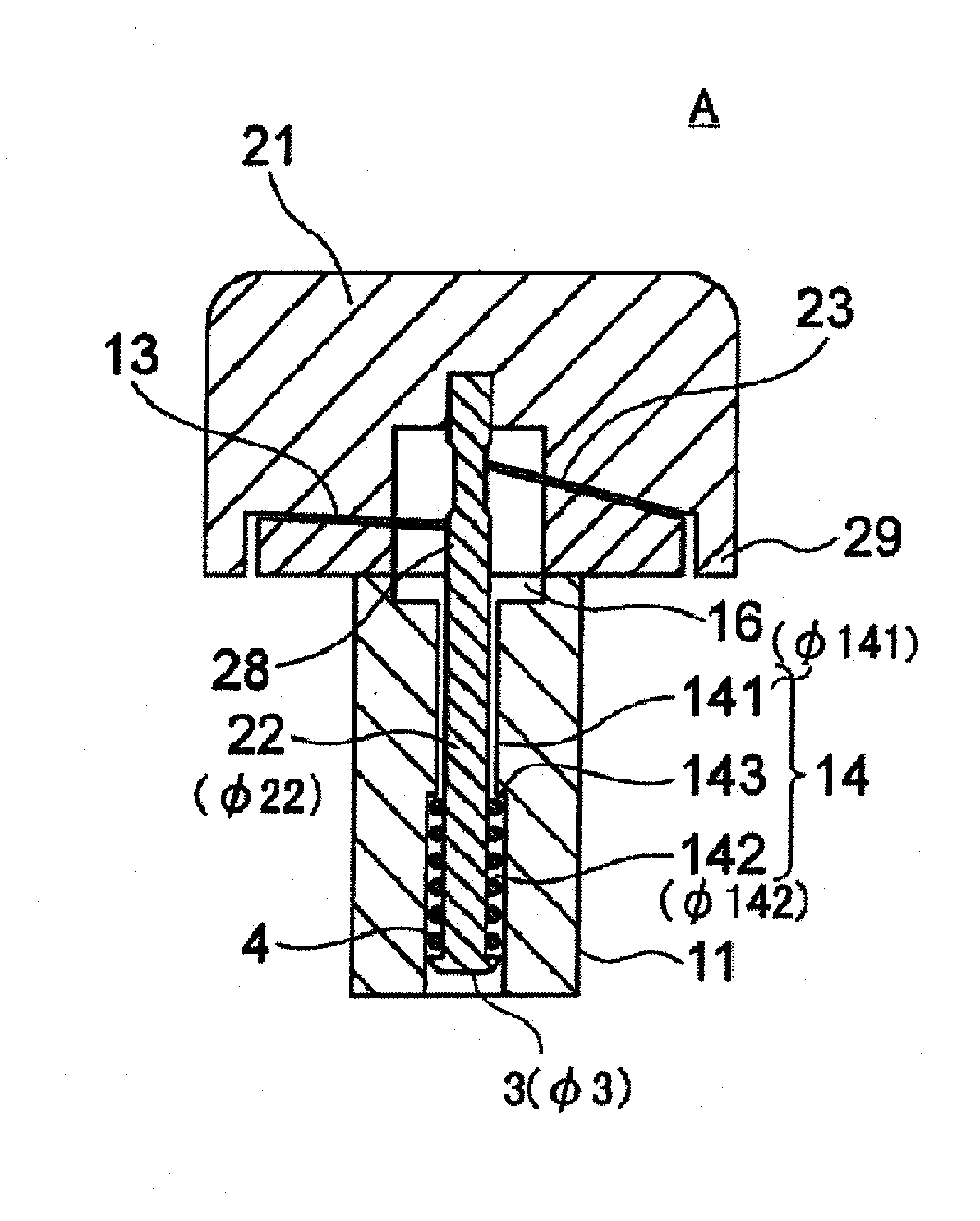
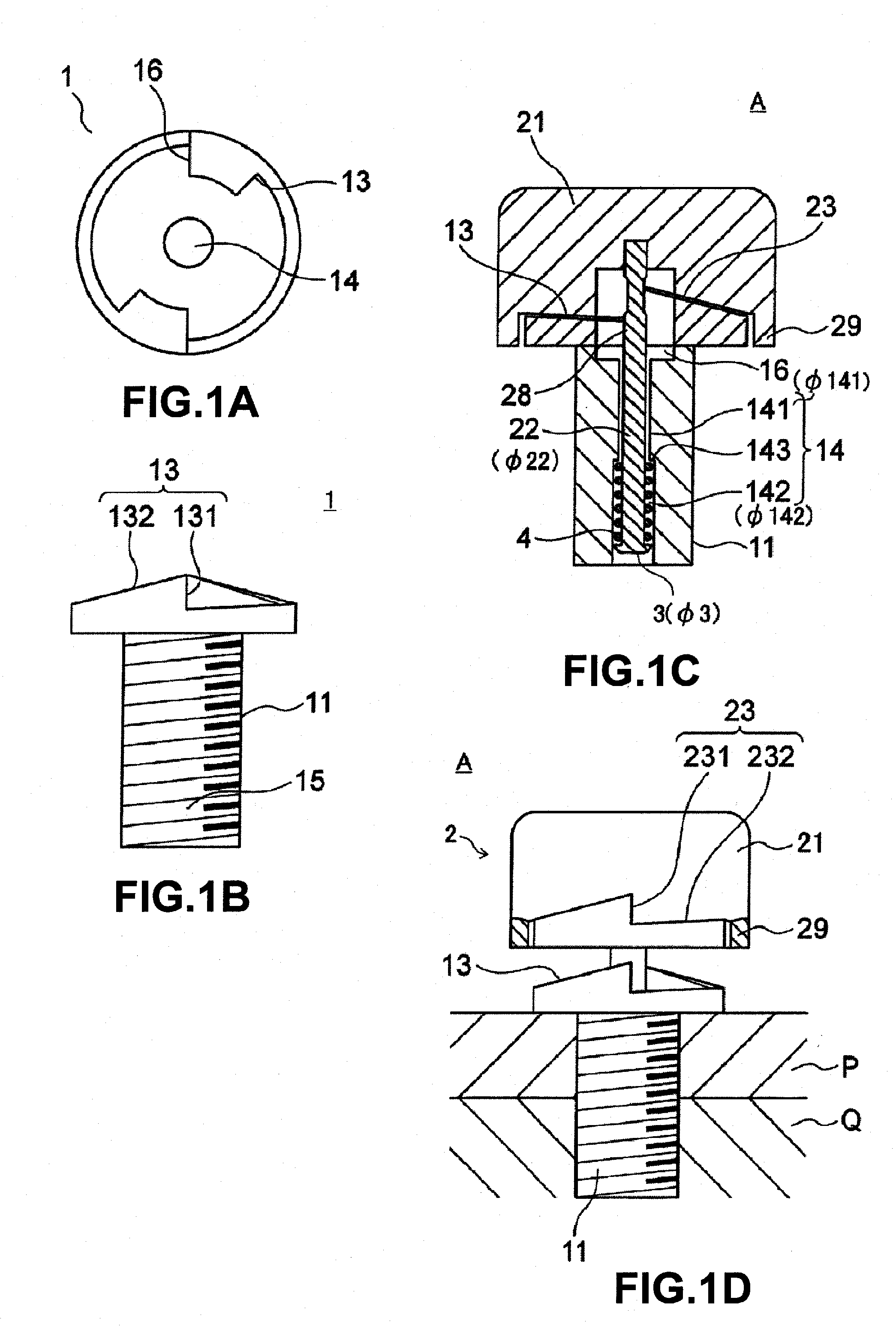
[0020]A first embodiment of a bolt of the present invention will be explained in detail with reference to FIGS. 1(A) to (D).

[0021]FIG. 1(A) is a top view of a fastened bolt, FIG. 1(B) is a front view of the fastened bolt, FIG. 1(C) is a cross-sectional view of the bolt, and FIG. 1(D) is a partially cutaway side view which shows a state where the bolt is fastened with clamped components.

[0022]A bolt A in the first embodiment of the present invention is configured by a fastened bolt 1, a fastening bolt 2, and a lock portion 3 which is provided in a lower end portion of a fastening shank (shaft) 22 of the fastening bolt 2.

[0023]As shown in FIG. 1(D), when the fastened bolt 1 is screwed into two clamped components P and Q, and is once clamped by a rotation of the fastening bolt 2 and the resultant rotation of the fastened bolt 1, the two clamped components P and Q are fastened. The fastened bolt 1, as shown in the front view of FIG. 1(B) and cross-sectional view of FIG. 1(C), is configu...

second embodiment

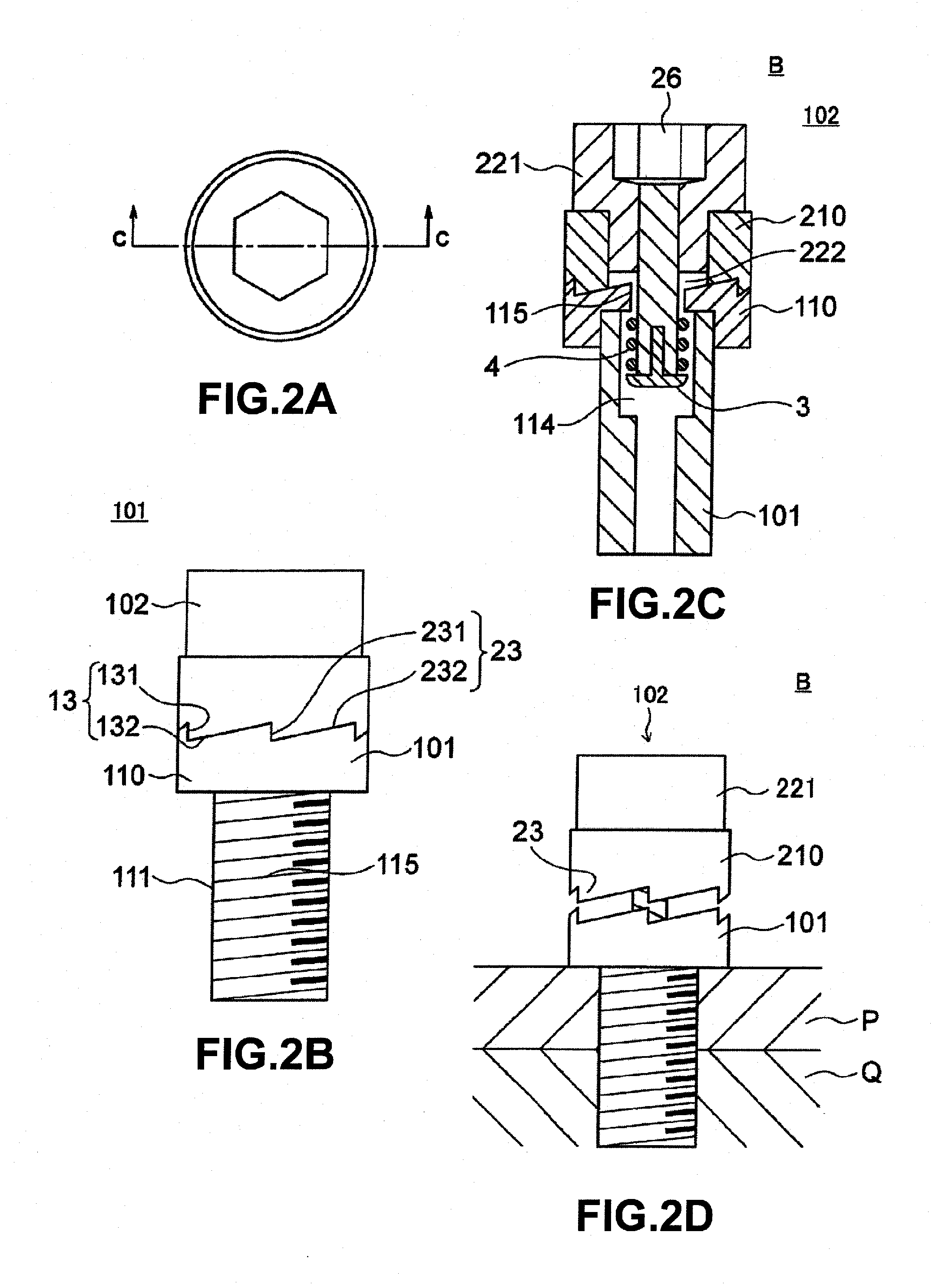
[0061]A second embodiment of the bolt in the present invention will be explained in detail with reference to FIGS. 2(A) to (D).

[0062]FIG. 2(A) is a top view of a bolt B in the second embodiment, FIG. 2(B) is a front view of the bolt B, FIG. 2(C) is a cross-sectional view of the bolt B, and FIG. 2(D) is a partially cutaway side view which shows a state where the bolt B is fastened with the clamped components.

[0063]The bolt B in the second embodiment of the present invention is configured by a fastened bolt 101, a fastening bolt 102, and a lock portion 3. The fastened bolt 101 is screwed together with two clamped components P and Q as shown in FIG. 2(D).

[0064]Note that, below, sometimes parts the same as the first embodiment will be assigned the same reference notations and explanations thereof will be omitted.

[0065]The fastened bolt 101, as shown in the front view of FIG. 2(B) and cross-sectional view of FIG. 2(C), is configured by a fastened bolt shank 111, a first serration 110 whi...

third embodiment

[0110]In a third embodiment shown in FIG. 5, grooves 51 and 52 are provided in place of the notch 50.


PUM


Abstract

A bolt capable of fastening without use of a special tool and which is extremely hard to be loosened (detached) after fastening is provided. A bolt of the present invention is configured by a fastened bolt, a fastening bolt, and a lock portion. A first engagement portion is provided on one end of a fastened bolt shank, and a concave portion is provided in the center part of the bolt shank. The fastening bolt has a second engagement portion on the surface confronting the first engagement portion and a fastening shank which is slidably inserted into the concave portion. The bolt is configured so that when the fastening bolt is turned in only one direction, the first engagement portion and the second engagement portion are engaged to turn the fastened bolt, but when the clamp load rotating the fastened bolt in only one direction reaches a predetermined torque, the lower strength portion is damaged so that the clamp load of the fastening bolt is not transferred to the fastened bolt.

Description

TECHNICAL FIELD[0001]The present invention relates to a bolt which is screwed into clamped components, more particularly relates to a bolt which is extremely hard to be detached from the clamped components after the bolt is once screwed into the clamped components.BACKGROUND ART[0002]For example, there have been proposed bolts for attaching a license plate to a vehicle, bolts for attaching a lid upon a U-shaped gutter, and other various types of bolts which are hard to be detached from the clamped components for the purpose of, for example, burglar-proofing after two or more clamped components are fastened. However, all known bolts have merits and demerits, so room for improvement is left.[0003]The present inventors previously proposed the bolts described in PLT (Patent Literature) 1 and PLT 2 as well.[0004]The bolts disclosed in PLT 1 and PLT 2 are configured so that once a fastened bolt and a fastening bolt are fastened, the both bolts cannot be detached from a clamped component a...

Claims


Application Information

Patent Timeline
IPC IPC(8): F16B31/02
CPCF16B31/027F16B39/28F16B41/00F16B23/0076F16B23/00F16B35/00F16B35/002
Inventor HASEGAWA, KENJI
Owner LOCKN BOLT
Why Eureka
Try Eureka