
Electronic device with environmental monitoring

a technology of environmental monitoring and electronic devices, applied in the direction of optical radiation measurement, volume metering, instruments, etc., can solve the problems of affecting the entry and change of barriers, unable to enhance computing capabilities of the majority of existing background electronic devices in people's homes, offices and vehicles, and unable to connect to the network subsystem

Inactive Publication Date: 2015-07-02
LEEO
View PDF3 Cites 27 Cited by
  • Summary
  • Abstract
  • Description
  • Claims
  • Application Information

AI Technical Summary

Benefits of technology

The described environmental monitoring device includes an imaging device that provides imaging data for the external environment. The imaging data has different spatial resolution in different regions of the external environment, which defines the field of view of the imaging device. The device also includes an angular adjustment mechanism that selectively rotates about an axis to change the orientation of the field of view. The device can detect motion, light scattering patterns, and light intensity in the field of view. The device can determine a metric based on the imaging data. The technical effect of the invention is to allow for multi-resolution imaging and field adjustment for improved environmental monitoring and detection.

Problems solved by technology

However, the overwhelming majority of the existing background electronic devices in people's homes, offices and vehicles have neither enhanced computing capabilities (such as processor that can execute a wide variety of applications) nor networking subsystems.
These barriers to entry and change are obstacles to widely implementing the Internet of things.
As a consequence, it may also be difficult to extend the advantages of connectivity and enhanced computing capabilities into these environments.
In addition, many of the existing background electronic devices used in people's homes, offices and vehicles are difficult to use.
For example, it is often challenging to replace a battery or to modify the functions of these existing background electronic devices.

Method used


Image

  • Electronic device with environmental monitoring
  • Electronic device with environmental monitoring
  • Electronic device with environmental monitoring

Examples


Embodiment Construction

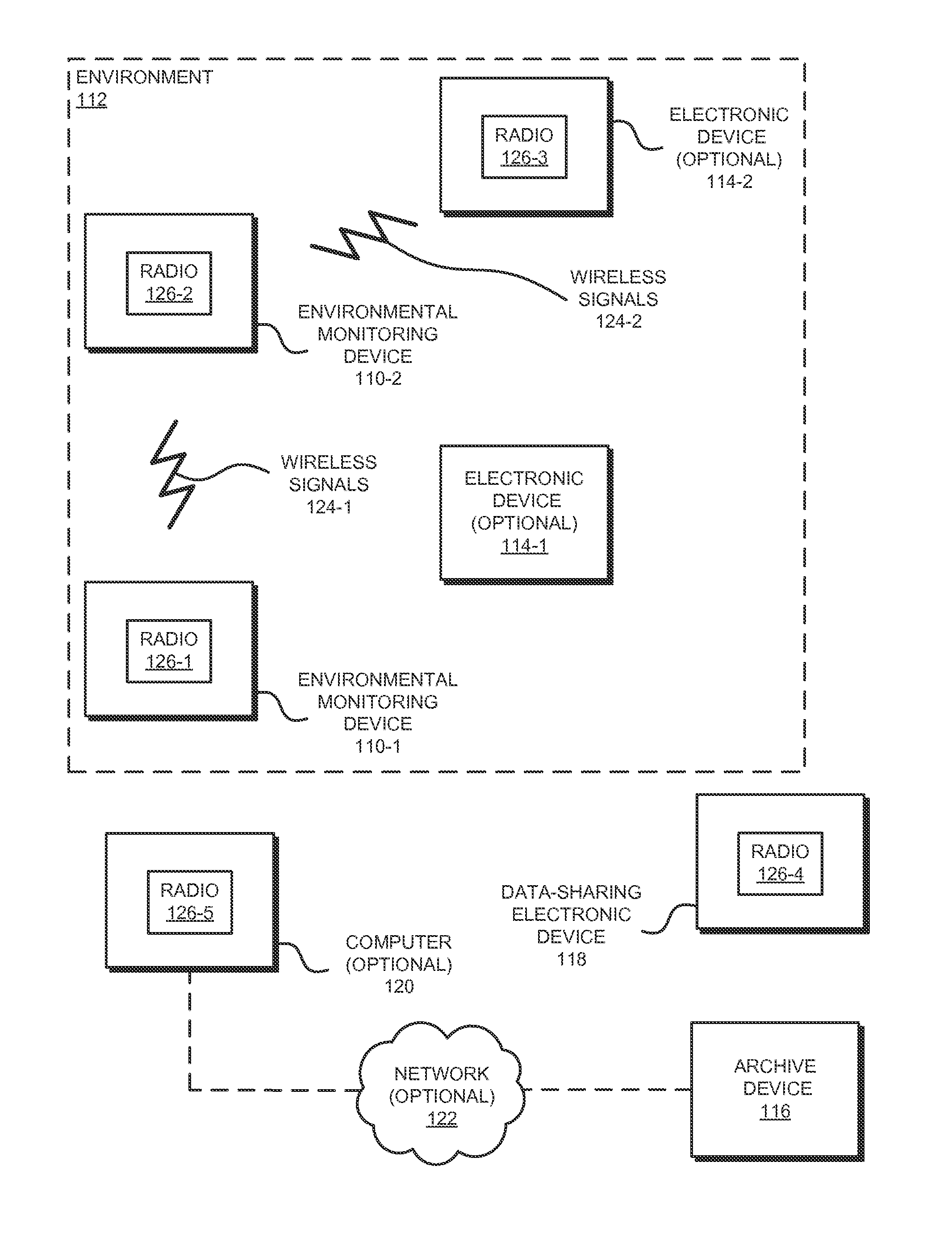
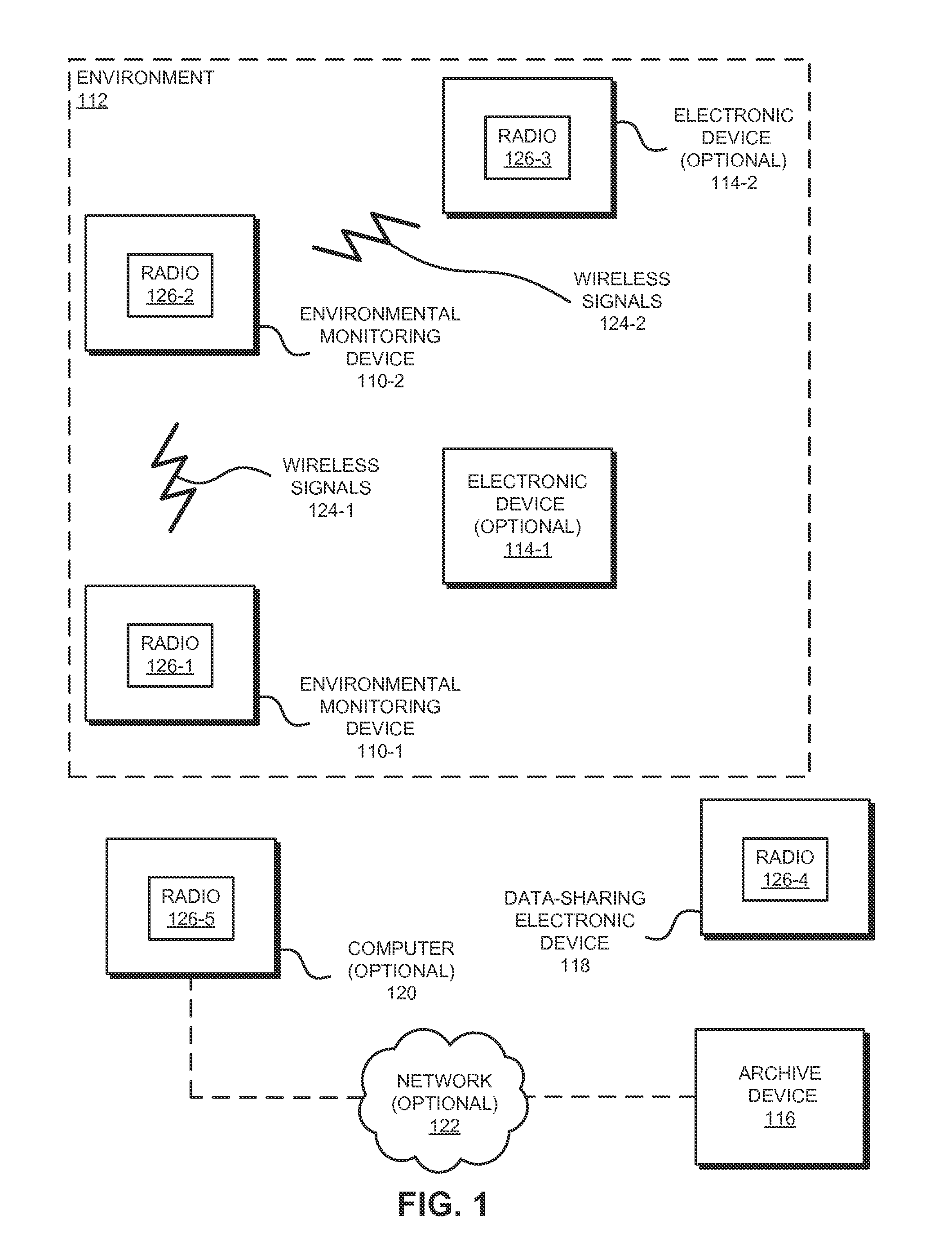
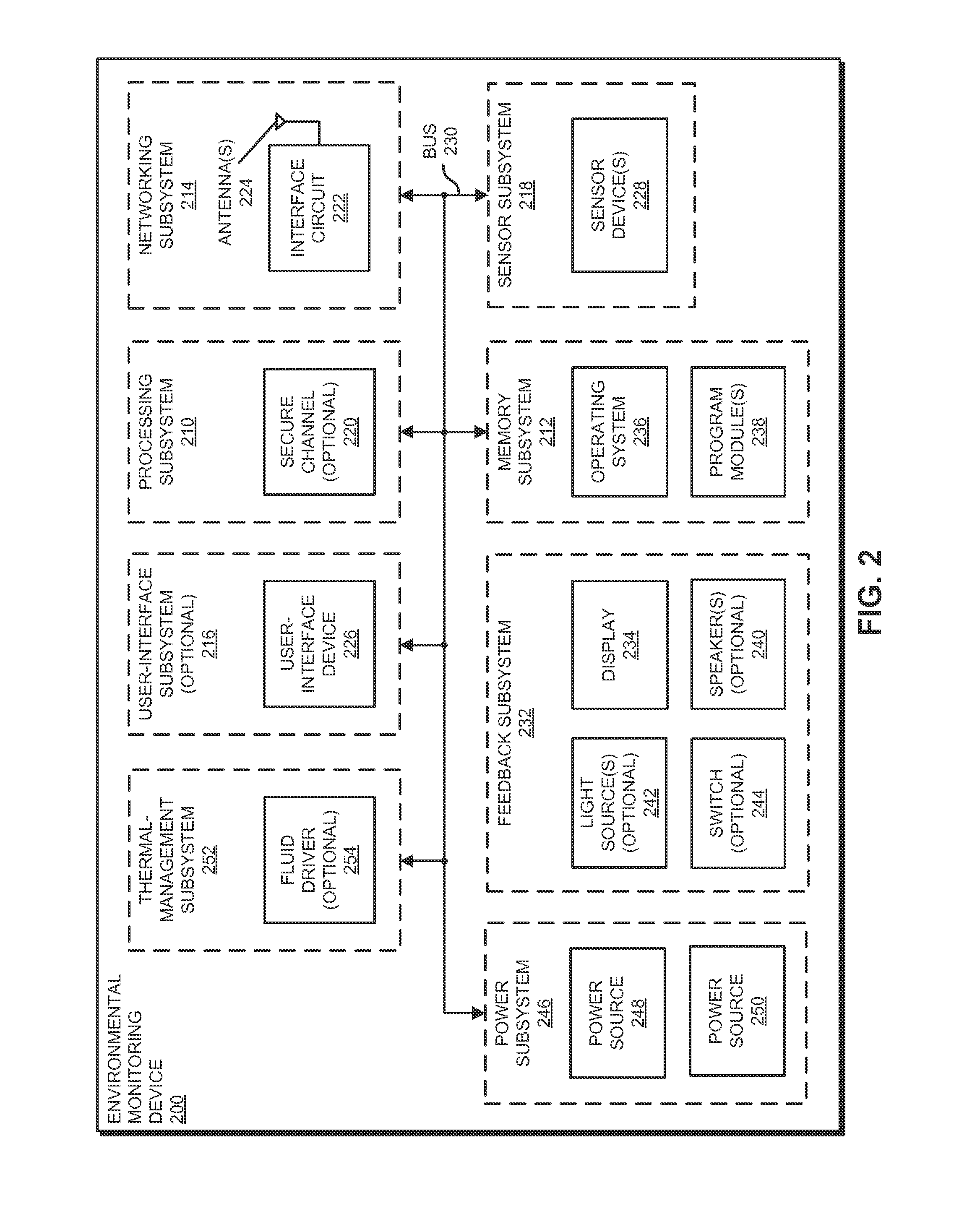
[0049]An environmental monitoring device that includes an imaging device is described. During operation of the environmental monitoring device, the imaging device provides imaging data for an external environment that includes the environmental monitoring device. Moreover, the imaging device has different spatial resolution in different regions of the external environment, which defines a field of view of the imaging device. For example, the imaging device may include a lens with a predefined distortion that provides the different spatial resolution, such as Fresnel lens. Alternatively, a mechanical stop may provide the different spatial resolution. Furthermore, the environmental monitoring device may include an angular adjustment mechanism that, in response to an external force or a control signal from a control mechanism in the environmental monitoring device, selectively rotates about an axis to change an orientation of the field of view.

[0050]In this way, the environmental monit...


PUM


Abstract

An environmental monitoring device that includes an imaging device is described. During operation of the environmental monitoring device, the imaging device provides imaging data for an external environment that includes the environmental monitoring device. Moreover, the imaging device has different spatial resolution in different regions of the external environment, which defines a field of view of the imaging device. For example, the imaging device may include a lens with a predefined distortion that provides the different spatial resolution, such as Fresnel lens. Alternatively, a mechanical stop may provide the different spatial resolution. Furthermore, the environmental monitoring device may include an angular adjustment mechanism that, in response to an external force or a control signal from a control mechanism in the environmental monitoring device, selectively rotates about an axis to change an orientation of the field of view.

Description

CROSS REFERENCE TO RELATED APPLICATION[0001]This application claims priority under 35 U.S.C. §120 as a Continuation-in-Part patent application of U.S. patent application Ser. No. 14 / 283,075, “Electronic Device with Environmental Monitoring,” by Adam M. Gettings, Andrew G. Stevens, and Bjorn Hovland, Attorney docket number LEEO-N-Z002.00-US, filed on May 20, 2014, which claims priority under 35 U.S.C. §119(e) to: U.S. Provisional Application Ser. No. 61 / 847,079, entitled “Lighting Device with Environmental Monitoring System,” by Adam M. Gettings, Eddy Y. Chan, Andrew G. Stevens, and Bjorn H. Hovland, Attorney docket number LEEO-02, filed on Jul. 16, 2013; U.S. Provisional Application Ser. No. 61 / 847,555, entitled “Safety Detector with Environmental Monitoring System,” by Adam M. Gettings, Eddy Y. Chan, Andrew G. Stevens, and Bjorn H. Hovland, Attorney docket number LEEO-03, filed on Jul. 17, 2013; and U.S. Provisional Application Ser. No. 61 / 858,563, entitled “Switch with Environment...

Claims


Application Information

Patent Timeline
IPC IPC(8): G01N21/84
CPCG01N21/84G01N2201/02G01N2201/068G01N33/0031G08B19/005G08B21/12G01V8/00G01F5/00G01F15/185G01N33/0075G08B25/001G01J5/025G01J5/026G01J5/04
Inventor GETTINGS, ADAM M.STEVENS, ANDREW G.HOVLAND, BJORN H.
Owner LEEO
Learn More