Structured illuminating microscopy apparatus

a microscopy and apparatus technology, applied in closed circuit television systems, instruments, television systems, etc., can solve problems such as difficulty in performing observation at high speed

Active Publication Date: 2015-07-02
NIKON CORP
View PDF5 Cites 35 Cited by
  • Summary
  • Abstract
  • Description
  • Claims
  • Application Information

AI Technical Summary

Problems solved by technology

However, in order to observe one piece of super-resolved image, there is a need to acquire a plurality of pieces of modulated images, and to generate spectra of the respective modulated images, so that it is difficult to perform the observation at high speed.

Method used


Image

  • Structured illuminating microscopy apparatus
  • Structured illuminating microscopy apparatus
  • Structured illuminating microscopy apparatus

Examples


Embodiment Construction

[0050]Hereinafter, a structured illuminating microscopy apparatus will be described as an embodiment of the present invention.

[0051][Explanation of Apparatus]

[0052]First, a configuration of a structured illuminating microscopy apparatus will be described.

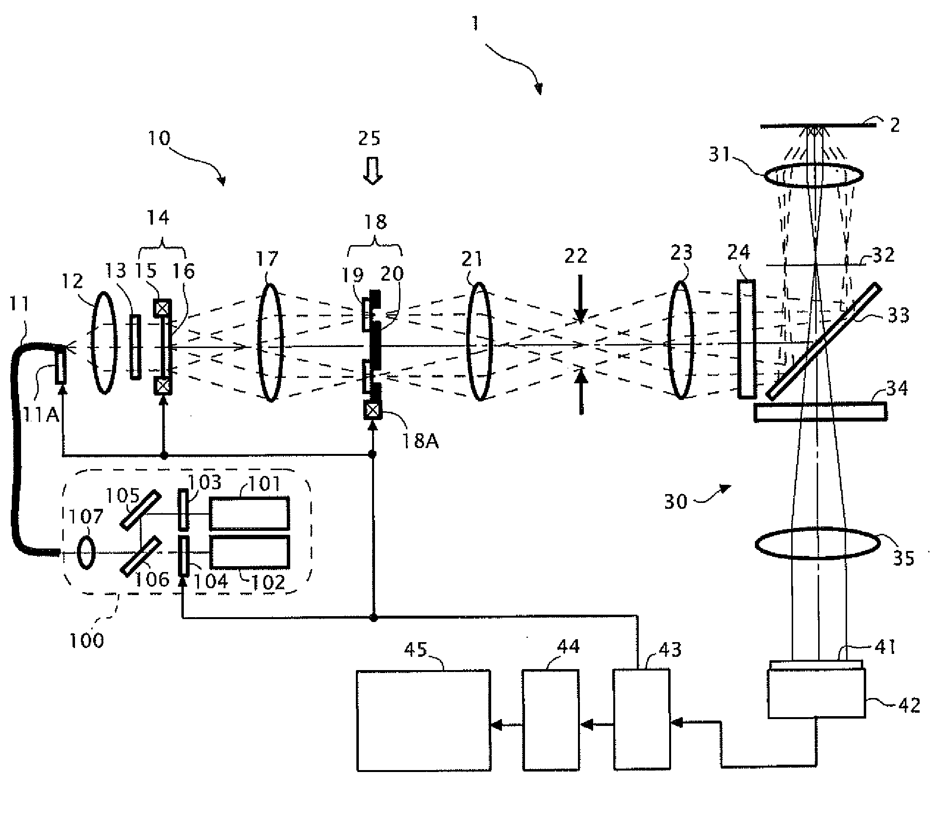
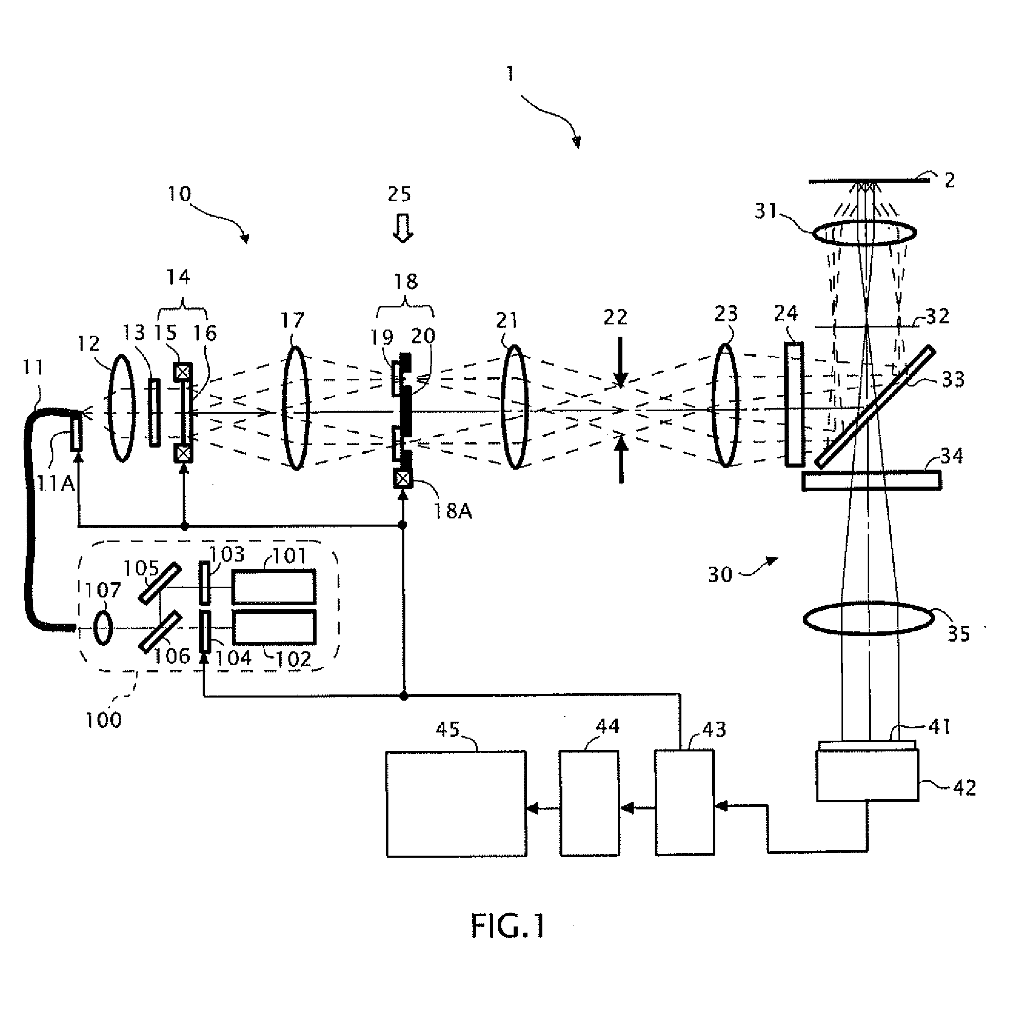
[0053]FIG. 1 is a configuration diagram of a structured illuminating microscopy apparatus 1. As illustrated in FIG. 1, there are provided, in the structured illuminating microscopy apparatus 1, a laser unit 100, an optical fiber 11, an illuminating optical system 10, an image-forming optical system 30, an imaging sensor 42, a controlling device 43, an image storing-calculating device 44, and an image displaying device 45. Note that the illuminating optical system 10 is one of epi-illumination type, and illuminates a sample 2 by utilizing an objective lens 31 and a dichroic mirror 33 of the image-forming optical system 30.

[0054]In the laser unit 100, there are provided a first laser light source 101, a second laser light source 102, ...


PUM


Abstract

An acquiring unit of a structured illuminating microscopy apparatus acquires at least two modulated images having the same wave number vector and the different phases; and a calculating unit of the structured illuminating microscopy apparatus, in a spatial frequency spectrum of each of at least the two modulated images acquired by the acquiring unit, separates a 0th-order modulating component and ±first-order modulating components of observational light fluxes superimposed on arbitrary two observation points based on at least four observation values regarding the two observation points which are mutually displaced by an amount of the wave number vector.

Description

CROSS-REFERENCE TO RELATED APPLICATION[0001]This application is a continuation application of International Application No. PCT / JP2013 / 004338, filed on Jul. 16, 2013, designating the U.S., and claims the benefit of priority from Japanese Patent Application No. 2012-160805, filed on Jul. 19, 2012, the entire contents of which are incorporated herein by reference.BACKGROUND[0002]1. Field[0003]The present application relates to a structured illuminating microscopy apparatus.[0004]2. Description of the Related Art[0005]As a method of performing a super-resolved observation on an observational object such as an organism sample, there is one in which a spatial frequency of a structure of the observational object is modulated by illuminating lights (refer to the specification of U.S. Pat. No. RE 38,307).[0006]In this method, the observational object is illuminated by the spatially-modulated illuminating lights, and information regarding a high spatial frequency that exceeds a resolution li...

Claims


Application Information

Patent Timeline
Patent Type & Authority Applications(United States)
IPC IPC(8): G02B21/36G02B21/06
CPCG02B21/365G02B21/06G02B21/361G02B21/367G02B27/58
Inventor OHKI, HIROSHINODA, TOMOYAOKUDAIRA, YOSUKE
Owner NIKON CORP
Why Eureka
Try Eureka