Piezoresistive sensor

Inactive Publication Date: 2015-07-02
HYUNDAI MOTOR CO LTD
View PDF4 Cites 14 Cited by
  • Summary
  • Abstract
  • Description
  • Claims
  • Application Information

AI Technical Summary

Benefits of technology

The patent text describes an improvement to a piezoresistive sensor by using a piezoresistive pattern that increases the deformation rate. This increase in deformation rate helps to improve the accuracy of the measurement. In simple terms, this means that the sensor can measure with greater precision even under the same force and torque.

Problems solved by technology

However, the aforementioned manner can cause errors, and these errors result in measurement inaccuracies within a range of 2% to 5%.

Method used


Image

  • Piezoresistive sensor
  • Piezoresistive sensor
  • Piezoresistive sensor

Examples


Embodiment Construction

[0015]The contents of the present disclosure will be described more fully hereinafter with reference to the accompanying drawings, in which exemplary embodiments of the disclosure are shown. As those skilled in the art would realize, the described embodiments may be modified in various different ways, all without departing from the spirit or scope of the present disclosure.

[0016]Throughout this specification and the claims that follow, when it is described that an element is “coupled” to another element, the element may be “directly coupled” to the other element or “electrically coupled” to the other element through a third element. In addition, unless explicitly described to the contrary, the word “comprise” and variations such as “comprises” or “comprising” will be understood to imply the inclusion of stated elements but not the exclusion of any other elements.

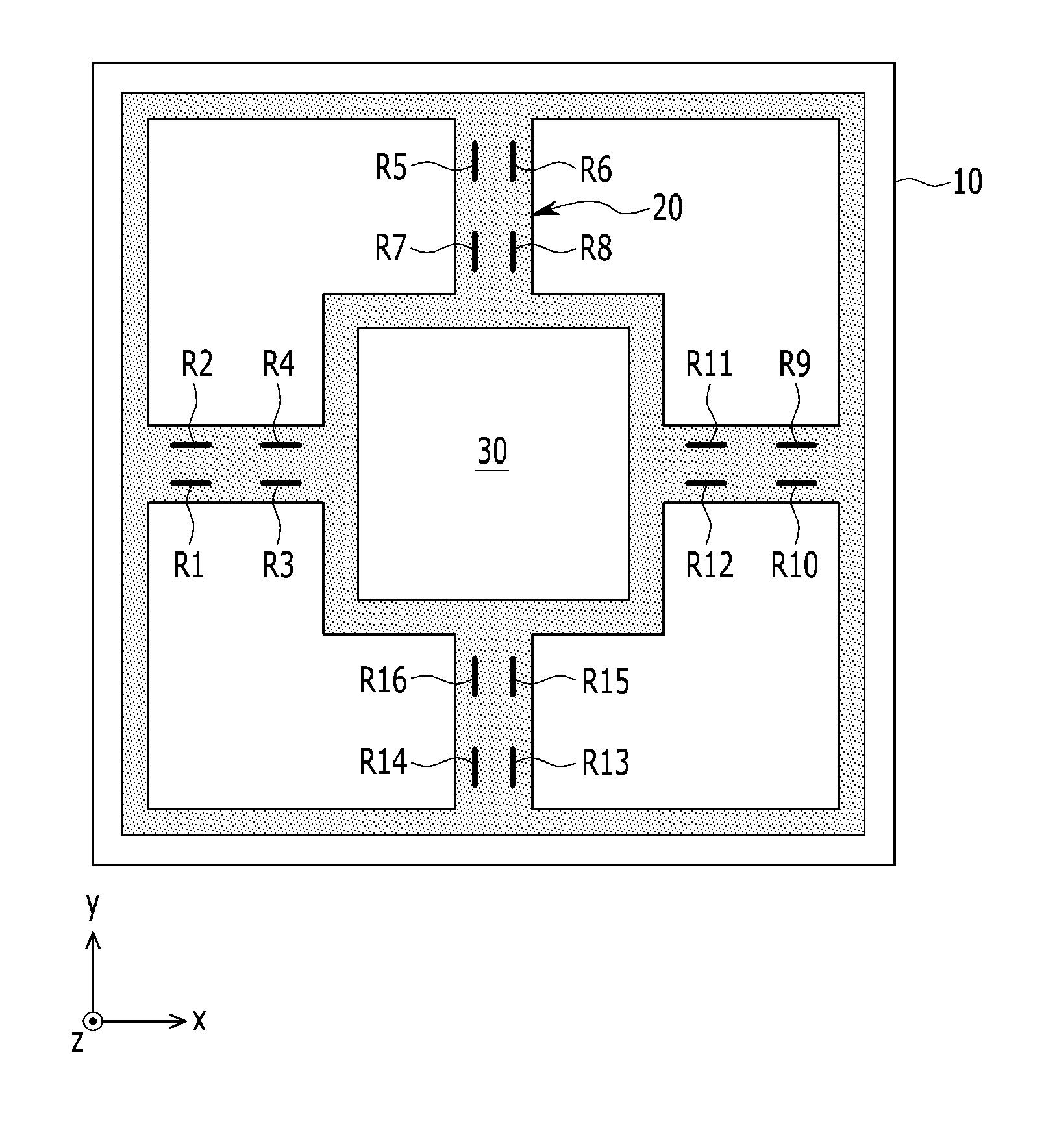
[0017]FIG. 1 is a top plan view schematically illustrating a piezoresistive sensor according to an embodiment of the prese...


PUM


Abstract

The present disclosure relates to a piezoresistive sensor that improves measurement precision by using a piezoresistive pattern that increases a piezoresistive deformation rate. An embodiment of the present disclosure provides a piezoresistive sensor that may include: a semiconductor substrate, four beams formed as a cross-shape with reference to a central body of the semiconductor substrate, and sixteen piezoresistive patterns formed on a top of the four beams, wherein sixteen piezoresistive patterns are formed as an “X” shape and are disposed on the four beams so as to form four piezoresistive pattern groups.

Description

CROSS-REFERENCE TO RELATED APPLICATION[0001]This application claims priority to and the benefit of Korean Patent Application No. 10-2013-0165486 filed in the Korean Intellectual Property Office on Dec. 27, 2013, the entire contents of which are incorporated herein by reference.BACKGROUND[0002](a) Technical Field[0003]The present disclosure relates to a piezoresistive sensor. More particularly, the present disclosure relates to the piezoresistive sensor that improves measurement precision by using a piezoresistive pattern increasing a piezoresistive deformation rate.[0004](b) Description of the Related Art[0005]In general, a six-axis force-torque sensor has a plurality of strain gauges that are attached to a structural body, which generate mechanical deformation and measure applied force and torque. In this manner, the strain gauges need to be attached in consideration of a direction in which force is applied, and in a position at which maximum deformation occurs. However, the aforem...

Claims


Application Information

Patent Timeline
IPC IPC(8): H01L29/84
CPCH01L29/84G01L1/18G01L5/162G01L5/167
Inventor KIM, DONG GULEE, YONG SUNGLEE, HIWON
Owner HYUNDAI MOTOR CO LTD
Why Eureka
Try Eureka