Rotational Impact Tool

a technology of rotating impact and tool, which is applied in the direction of power-driven tools, manufacturing tools, etc., can solve the problems of large rearward movement of the hammer, noise and vibration, and collision of steel balls with the cam end, so as to prolong the service life of the cam mechanism and reduce noise and vibration

Inactive Publication Date: 2015-07-09
HITACHI KOKI CO LTD
View PDF2 Cites 3 Cited by
  • Summary
  • Abstract
  • Description
  • Claims
  • Application Information

AI Technical Summary

Benefits of technology

[0018]The present invention described above can provide a rotational impact tool that can restrain noises and vibrations caused by cam

Problems solved by technology

When fastening a hard member, such as a bolt and a nut, to a workpiece, a large impact reaction force unavoidably occurs between the anvil and the hammer for hitting th

Method used


Image

  • Rotational Impact Tool
  • Rotational Impact Tool
  • Rotational Impact Tool

Examples


Embodiment Construction

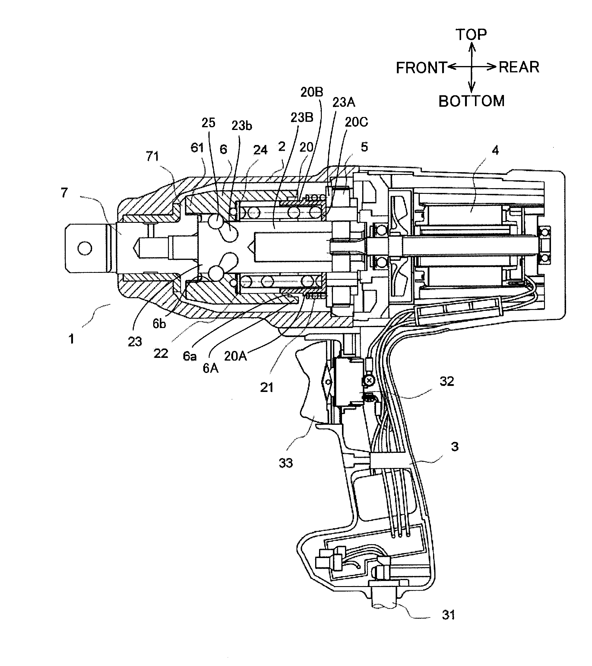
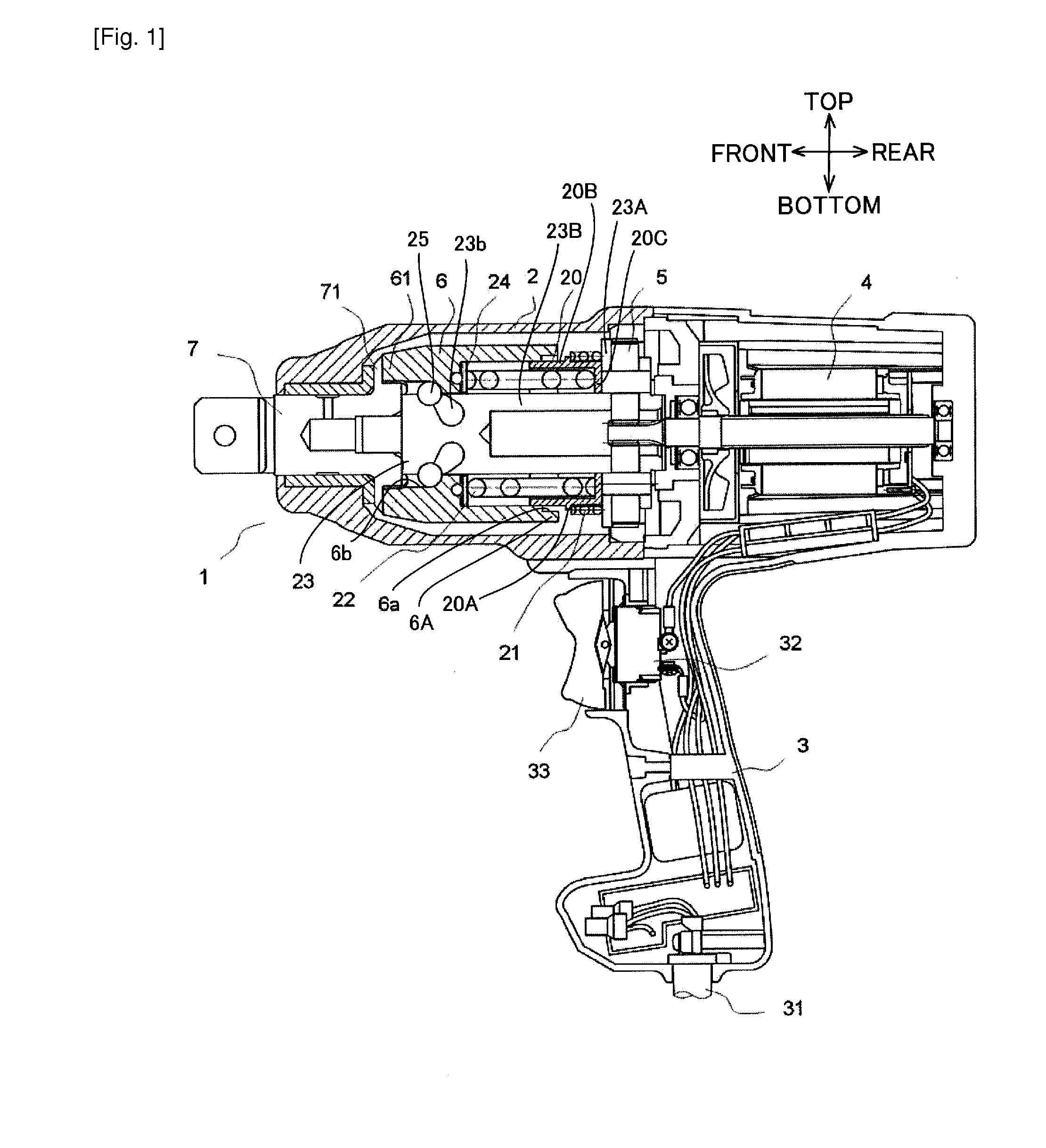
[0028]An impact wrench as a rotational impact tool according to one embodiment of the present invention will be described while referring to FIGS. 1 through 8 wherein like parts and components are designated by the same reference numerals to avoid duplicating description. Note that the rotational impact tool is not limited to the impact wrench, in so far as the tool includes a configuration for preventing the cam end collision.

[0029]The impact wrench 1 shown in FIG. 1 is a tool for fastening a screw, a bolt, a nut, and the like. As shown in FIG. 1, the impact wrench 1 mainly includes a main body housing 2, a handle housing 3, a motor 4, a gear mechanism 5, a hammer 6, and an anvil 7. The hammer 6 and the anvil 7 constitute an impact mechanism.

[0030]In the following description, the left side of the impact wrench 1 in FIG. 1 will be defined as the front side, while the right side in FIG. 1 will be defined as the rear side. In other words, the side where the anvil 7 is provided will b...


PUM


Abstract

A rotational impact tool including: a motor; a spindle; a hammer; a first resilient member; and an anvil. The motor generates a drive force. The spindle rotates in a rotating direction upon transmission of the drive force from the motor. The spindle has an axis extending in an axial direction that includes a first direction and a second direction opposite to the first direction. The hammer moves in the rotational direction and in the axial direction relative to the spindle to generate a rotational impact force. The first resilient member urges the hammer in the first direction. The anvil transmits the rotational impact force to an end bit. The rotational impact tool further includes a second resilient member. The second resilient member is disposed at a position radially outward of the first resilient member and is configured to abut the hammer when the hammer moves in the second direction.

Description

TECHNICAL FIELD[0001]The invention relates to a rotational impact tool for fastening a screw, a bolt, a nut and the like, to a workpiece.BACKGROUND ART[0002]An impact wrench as a rotational impact tool for fastening a screw, a bolt, a nut and the like to a workpiece is disclosed in Japanese Patent Application Publication No. 2012-66344. The rotational impact tool mainly includes a large-sized impact mechanism having a hammer and an anvil, a deceleration mechanism, and a spindle. The hammer is urged forward by a spring disposed between the deceleration mechanism and the spindle. When rotational resistance relative to the anvil becomes greater after the screw, for example, is seated, rotation of the anvil is restrained. Then, the hammer moves backward against the urging force by the spring to circumvent a projecting portion of the anvil and is accelerated to exert an impact on the anvil. By repeating this impact operation, the rotational impact force is continuously or intermittently ...

Claims


Application Information

Patent Timeline
IPC IPC(8): B25B21/02
CPCB25B21/02B25B21/026
Inventor TADOKORO, NAOKISAKAI, HIRONORI
Owner HITACHI KOKI CO LTD
Why Eureka
Try Eureka