Modular directional control valve

a directional control valve and module technology, applied in the direction of fluid removal, thin material handling, borehole/well accessories, etc., can solve the problems of unsuitability for fitting, large risk of incorrect assembly, and bulky known directional control valves

Active Publication Date: 2015-07-09
PROSERV GILMORE VALVE LLC
View PDF8 Cites 15 Cited by
  • Summary
  • Abstract
  • Description
  • Claims
  • Application Information

AI Technical Summary

Benefits of technology

[0006]The present disclosure generally relates to a modular directional control valve. In one embodiment, a directional control valve includes: a base and a slider longitudinally movable relative to the base. The base includes: a rectangular body having a longitudinal bore, a transverse bore, and a chamber formed at an intersection between the bores; a supply seal plate having a first stinger disposed in the transverse bore, a first receptacle, and a passage extending from the first receptacle through the first stinger; a supply block fastened to the body and having a second stinger disposed in the first receptacle and a first coupling for connection to a flow line; a function seal plate having a third stinger disposed in the transverse bore, second and third receptacles, and passages extending from the second and third receptacles through the third stinger; and first and second function blocks fastened to the body and having respective fourth and fifth st

Problems solved by technology

Known directional control valves are complex to assemble leading to substantial risk of incorrect assembly.
Known directio

Method used


Image

  • Modular directional control valve
  • Modular directional control valve
  • Modular directional control valve

Examples


Embodiment Construction

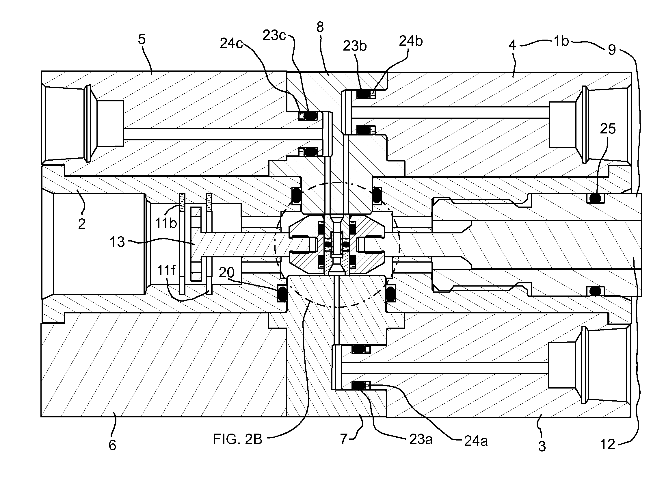
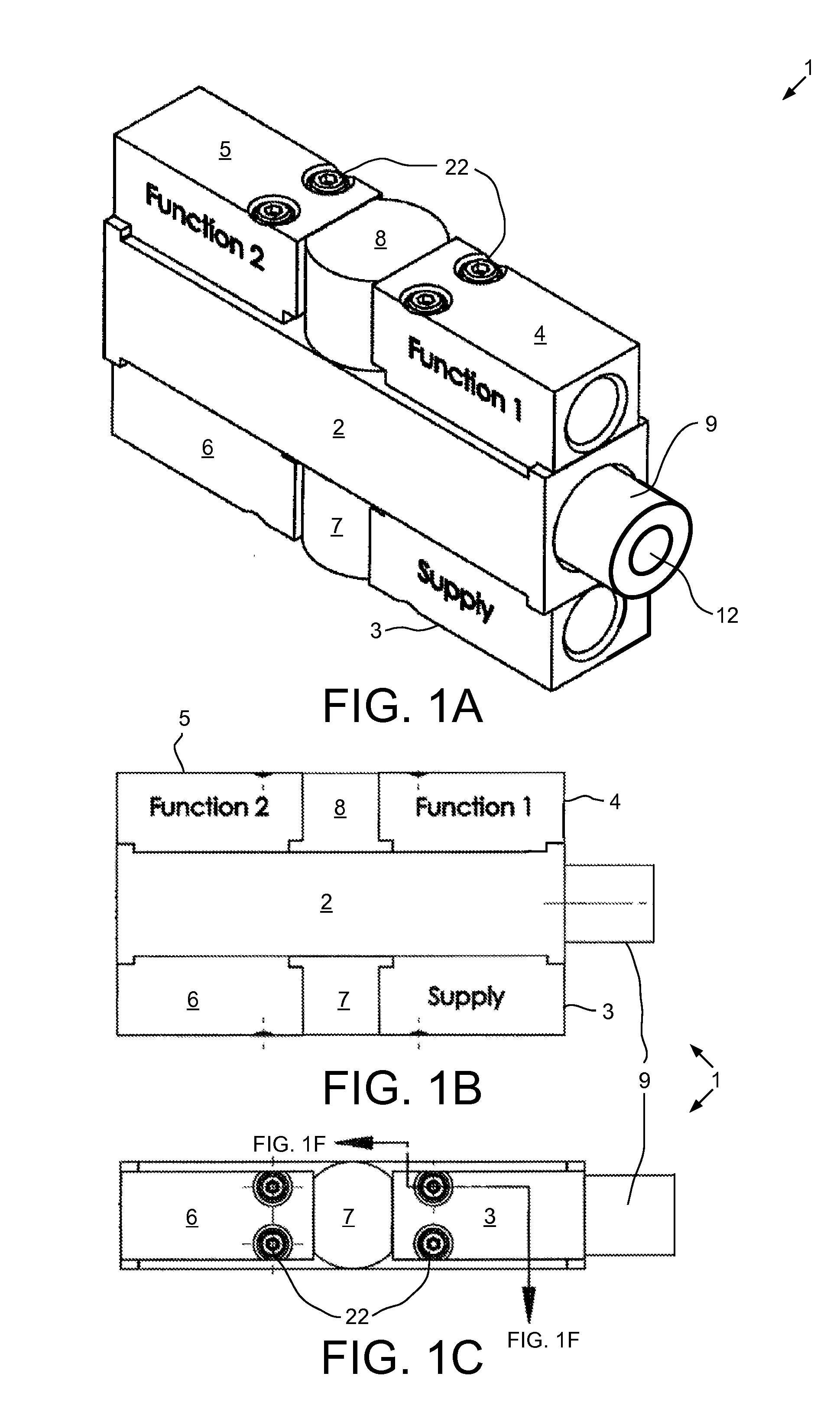
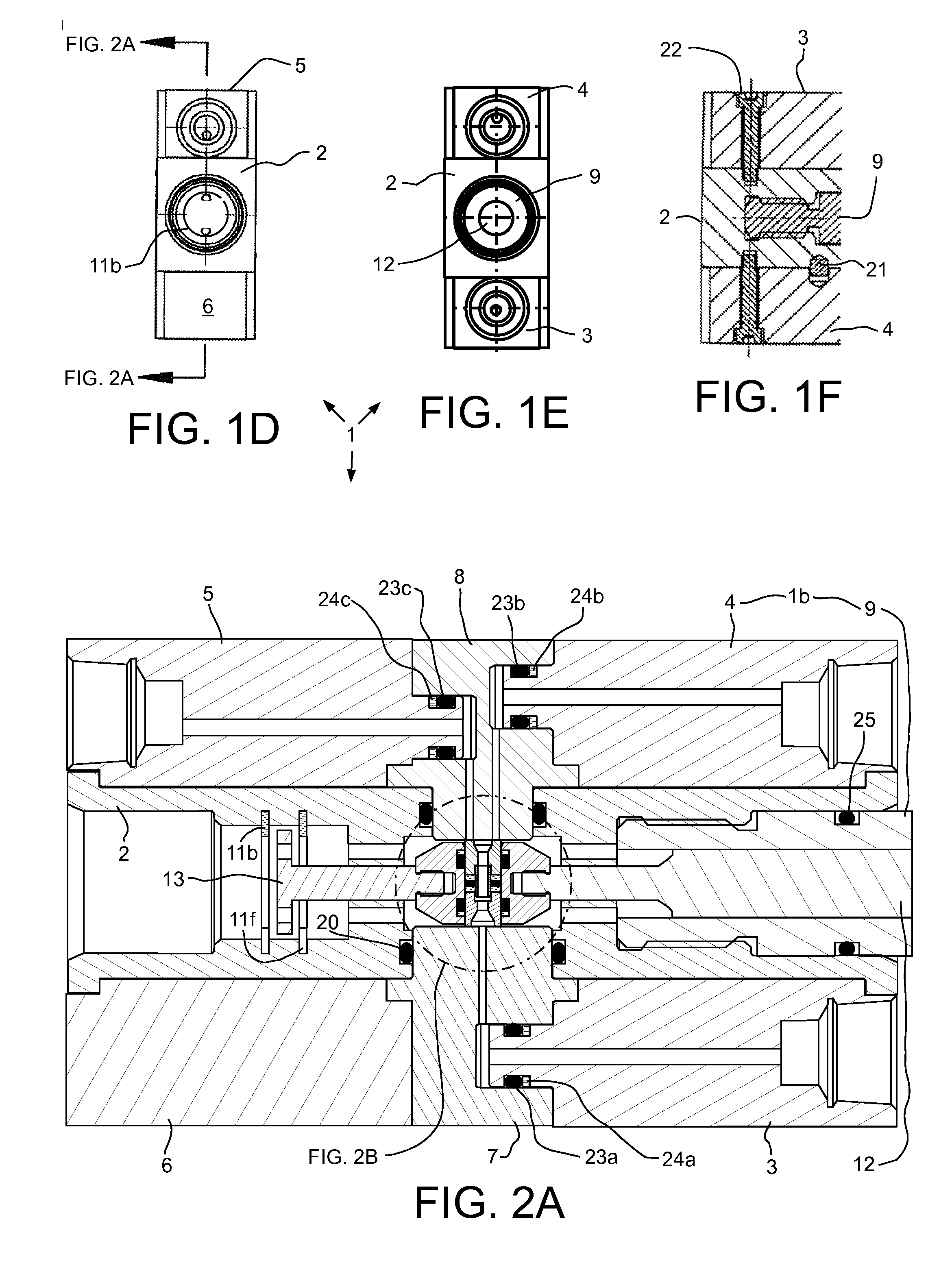
[0017]FIGS. 1A-1E are external views of a modular directional control valve 1, according to one embodiment of the present disclosure. FIG. 1F is a cross section of FIG. 1C. FIG. 2A is a cross section of FIG. 1D with the valve 1 in a closed position. FIG. 2B is an enlargement of FIG. 2A illustrating a sliding seal assembly 10 of the valve 1. FIG. 2C is an external view of the sliding seal assembly 10. Unless otherwise specified, parts, other than seals and backup rings, of the valve 1 may each be made from a high strength metal or alloy, such as steel, stainless steel, or nickel-chromium alloy. Unless otherwise specified, seals may be made from an elastomer or elastomeric copolymer. Backup rings may be made from an engineering polymer.

[0018]The valve 1 may include a base 1b and a slider 1s longitudinally movable relative to the base between the closed position (shown), a first function position (FIG. 3), and a second function position (FIG. 4). The base 1b may include a body 2, a sup...


PUM


Abstract

A directional control valve includes: a base and a slider longitudinally movable relative to the base. The base includes: a rectangular body having a longitudinal bore, a transverse bore, and a chamber formed at an intersection between the bores; supply and function seal plates, each having a stinger disposed in the transverse bore, one or more receptacles, and a passage extending from each receptacle through the stinger; and a supply, first function, and second function blocks, each fastened to the body and having a stinger disposed in the respective receptacle and a coupling for connection to a flow line. The slider includes: a sliding seal assembly disposed in the chamber; and an operating rod fastened to the seal assembly.

Description

BACKGROUND OF THE DISCLOSURE [0001]1. Field of the Disclosure[0002]The present disclosure generally relates to a modular directional control valve.[0003]2. Description of the Related Art[0004]Downhole tools are frequently used in the drilling and / or evaluation stage of a crude oil and / or natural gas well. Such tools may be operated by drilling fluid pumped down a drill string and / or via control signal sent down wireline. Such tools may also be in fluid communication with wellbore fluid. The operation of such tools may require an onboard directional control valve to selectively operate various functions of a single tool or various tools of a tool string, such as a bottomhole assembly. Known directional control valves are complex to assemble leading to substantial risk of incorrect assembly. Known directional control valves are also bulky making them unsuitable for fitting within walls of or annuli between oilfield tubulars.[0005]It is therefore desirable to provide a directional cont...

Claims


Application Information

Patent Timeline
IPC IPC(8): E21B34/10E21B34/06
CPCE21B34/066E21B34/101Y10T137/4807Y10T137/4857
Inventor WEINTRAUB, PRESTON
Owner PROSERV GILMORE VALVE LLC
Why Eureka
Try Eureka