Feedback from a welding torch of a welding system

a welding system and welding torch technology, applied in the field of welding systems, can solve the problems of insufficient welding operator training, limited number of welding training systems, and high acquisition and operation costs of training systems, and achieve the effect of welding operators, reducing the number of welding operators, and improving the quality of welding

Active Publication Date: 2015-07-09
ILLINOIS TOOL WORKS INC
View PDF26 Cites 84 Cited by
  • Summary
  • Abstract
  • Description
  • Claims
  • Application Information

AI Technical Summary

Benefits of technology

[0004]In one embodiment, a welding system includes a welding torch. The welding torch includes a sensor configured to detect a motion associated with the welding torch, a temperature associated with the welding torch, or some combination thereof. A display of the welding torch is activated, a determination is made that the welding torch has been involved in a high impact event, live welding using the welding torch is disabled, a software selection is made, or some combination thereof, based on the motion, the temperature, or some combination thereof.
[0005]In another embodiment, a method includes detecting a parameter corresponding to a welding operation using control circuitry. The method also includes determining whether the parameter is within a first predetermined range. The method includes vibrating the welding torch at a first pattern if the parameter is within the first predetermined range. The method also includes if the parameter is not within the first predetermined range, determining whether the parameter is within a second predetermined range. The method includes vibrating the welding torch at a second pattern if the parameter is within the second predetermined range. The second pattern is different than the first pattern.

Problems solved by technology

As may be appreciated, these training systems may be expensive to acquire and operate.
Accordingly, welding training institutions may only acquire a limited number of such training systems.
Furthermore, certain welding systems may not adequately train welding operators to perform high quality welds.

Method used


Image

  • Feedback from a welding torch of a welding system
  • Feedback from a welding torch of a welding system
  • Feedback from a welding torch of a welding system

Examples


Embodiment Construction

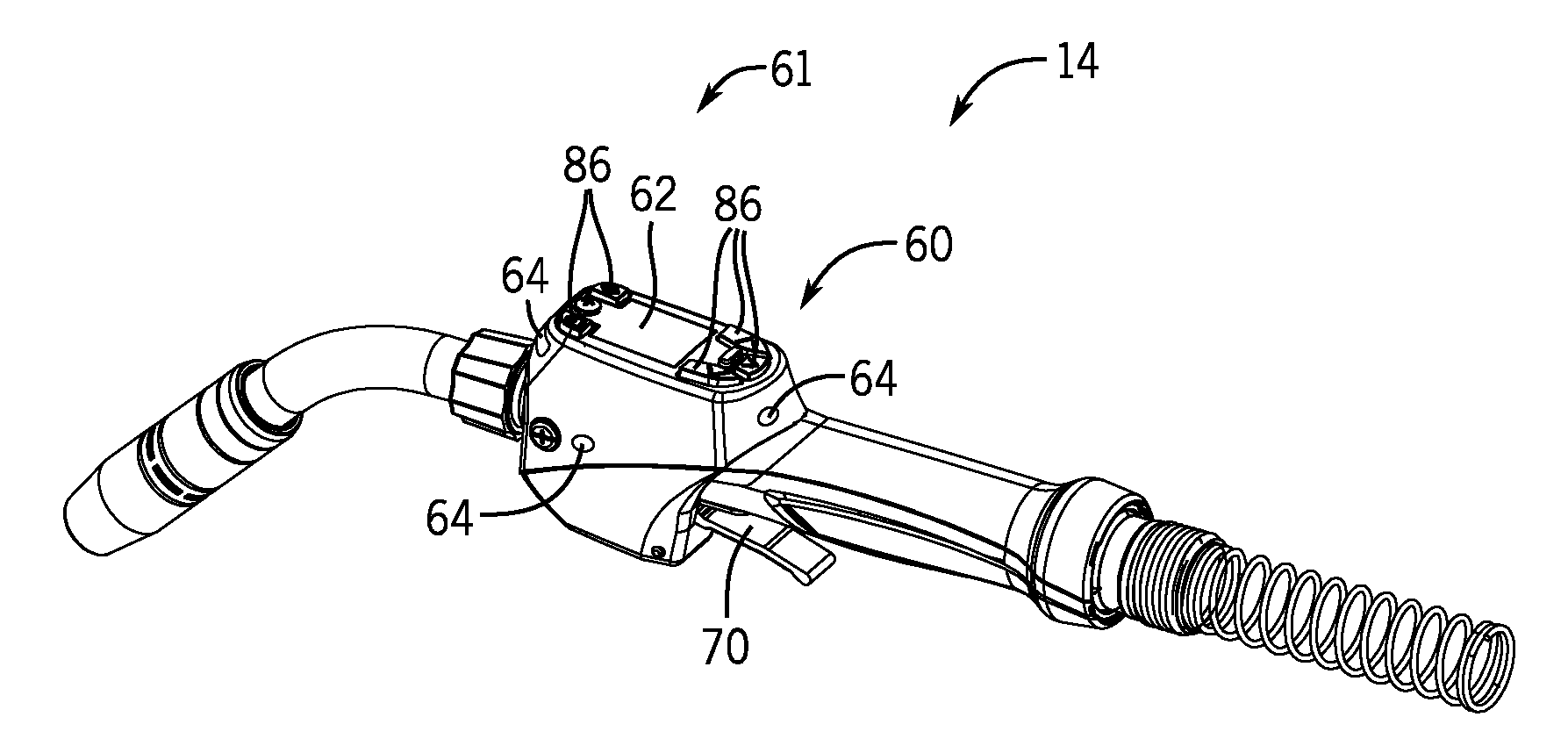
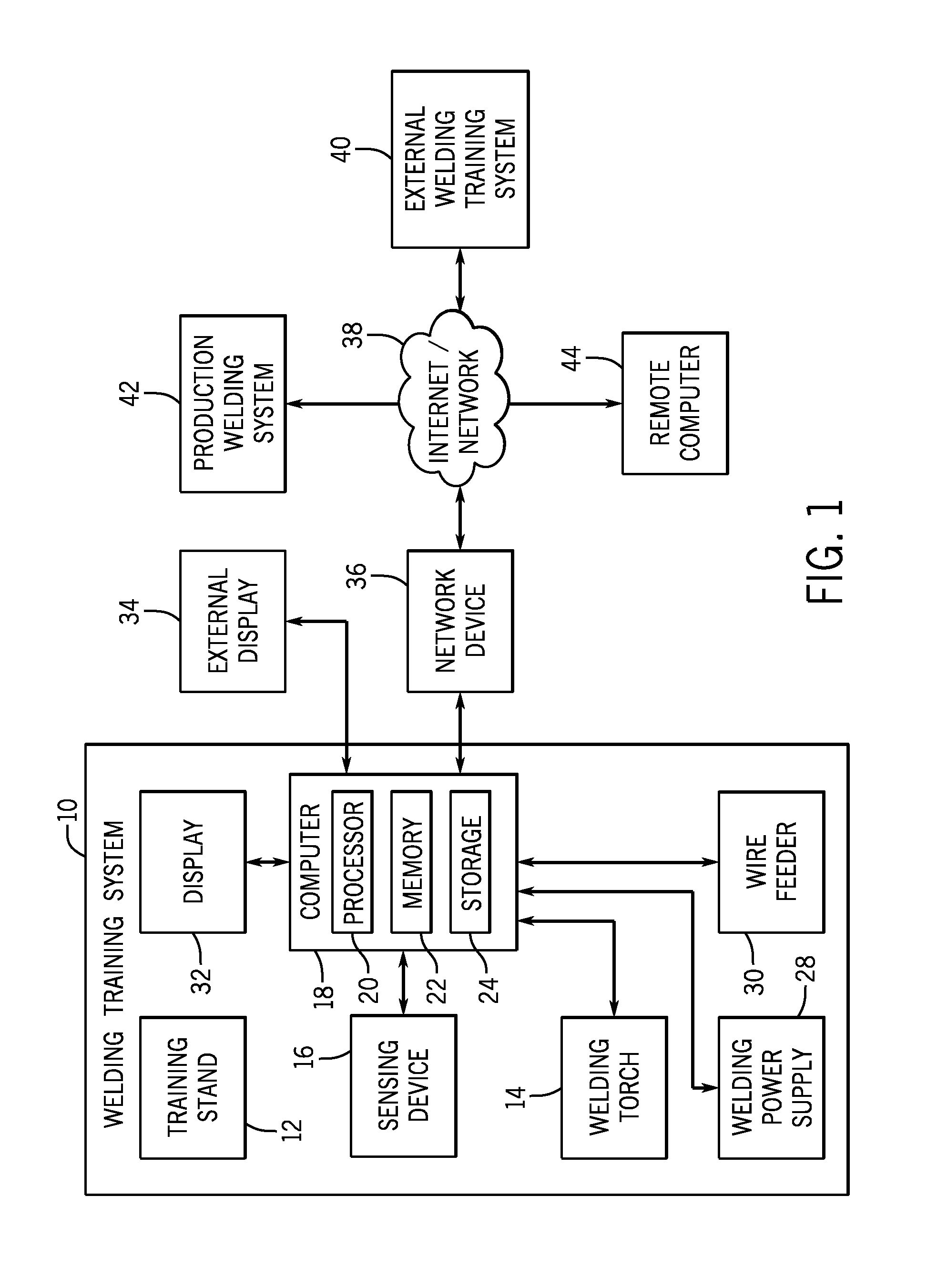
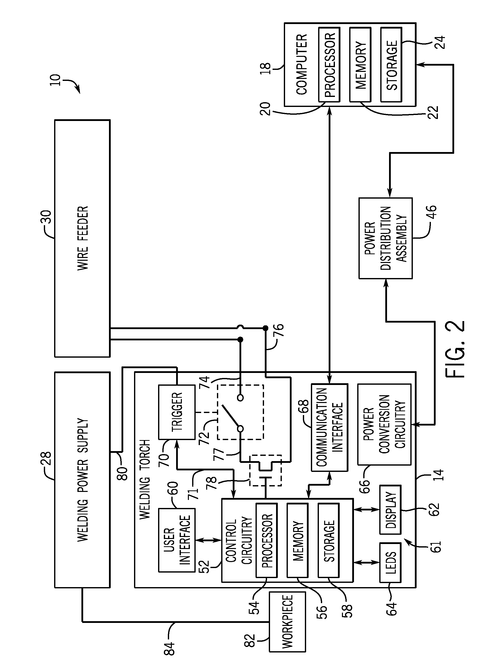
[0057]FIG. 1 is a block diagram of an embodiment of a welding system 10. As used herein, a welding system may include any suitable welding related system, including, but not limited to, a welding training system, a live welding system, a simulated welding system, a virtual reality welding system, and so forth. The welding system 10 includes a welding stand 12 for providing support for various training devices. For example, the stand 12 may be configured to support a welding surface, a workpiece, a fixture, one or more training arms, and so forth. The welding system 10 also includes a welding torch 14 that may be used by a welding operator (e.g., welding student) to perform welding operations (e.g., training operations). As described in greater detail below, the welding torch 14 may be configured with a user interface configured to receive inputs from the welding operator, control circuitry configured to process the inputs, and a communication interface configured to provide the inpu...


PUM

PropertyMeasurementUnit
distanceaaaaaaaaaa
distanceaaaaaaaaaa
temperatureaaaaaaaaaa

Abstract

A welding system includes a welding torch. The welding torch includes a sensor configured to detect a motion associated with the welding torch, a temperature associated with the welding torch, or some combination thereof. A display of the welding torch is activated, a determination is made that the welding torch has been involved in a high impact event, live welding using the welding torch is disabled, a software selection is made, or some combination thereof, based on the motion, the temperature, or some combination thereof.

Description

BACKGROUND[0001]The invention relates generally to welding and, more particularly, to a welding system that may be used for training.[0002]Welding is a process that has increasingly become utilized in various industries and applications. Such processes may be automated in certain contexts, although a large number of applications continue to exist for manual welding operations. In both cases, such welding operations rely on a variety of types of equipment to ensure the supply of welding consumables (e.g., wire feed, shielding gas, etc.) is provided to the weld in appropriate amounts at the desired time.[0003]In preparation for performing manual welding operations, welding operators may be trained using a welding system (e.g., a welding training system). The welding system may be designed to train welding operators with the proper techniques for performing various welding operations. Certain welding systems may use various training methods. As may be appreciated, these training system...

Claims


Application Information

Patent Timeline
Patent Type & Authority Applications(United States)
IPC IPC(8): G09B19/24G09B9/00
CPCG09B9/00G09B19/24B23K9/0956B23K9/10B23K9/30B23K9/32B23K37/006
Inventor BECKER, WILLIAM J.WALKER, JAMES M.ERDMANN, JEREMY J.
Owner ILLINOIS TOOL WORKS INC
Why Eureka
Try Eureka