
System and method for inflation gas filtration through a tortuous flow pathway

Active Publication Date: 2015-07-16
AUTOLIV ASP INC
View PDF10 Cites 8 Cited by
  • Summary
  • Abstract
  • Description
  • Claims
  • Application Information

AI Technical Summary

Benefits of technology

The present invention is an airbag system and method that was developed to address the unsolved problems in the current airbag systems and methods. The invention provides reliable protection for vehicle occupants in a wide variety of collision situations while minimizing manufacturing and installation costs. The technical effect of the invention is to provide better protection for vehicle occupants in collisions and to reduce manufacturing and installation costs.

Problems solved by technology

Each of these parts adds significantly to the cost of the inflator.
Hence, the inflator typically makes up a large portion of the cost of an airbag assembly.
The quantity of steps involved not only further increases the cost of potential inflators, it also increases the likelihood of defects in material or workmanship in the finished inflator.

Method used


Image

  • System and method for inflation gas filtration through a tortuous flow pathway
  • System and method for inflation gas filtration through a tortuous flow pathway
  • System and method for inflation gas filtration through a tortuous flow pathway

Examples


Embodiment Construction

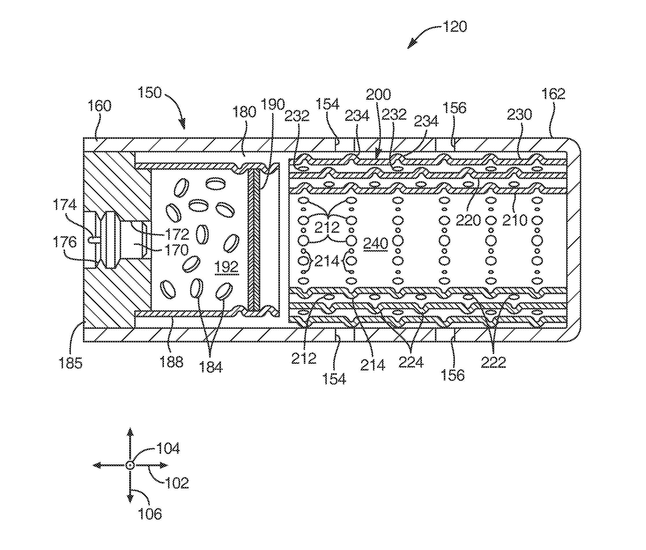
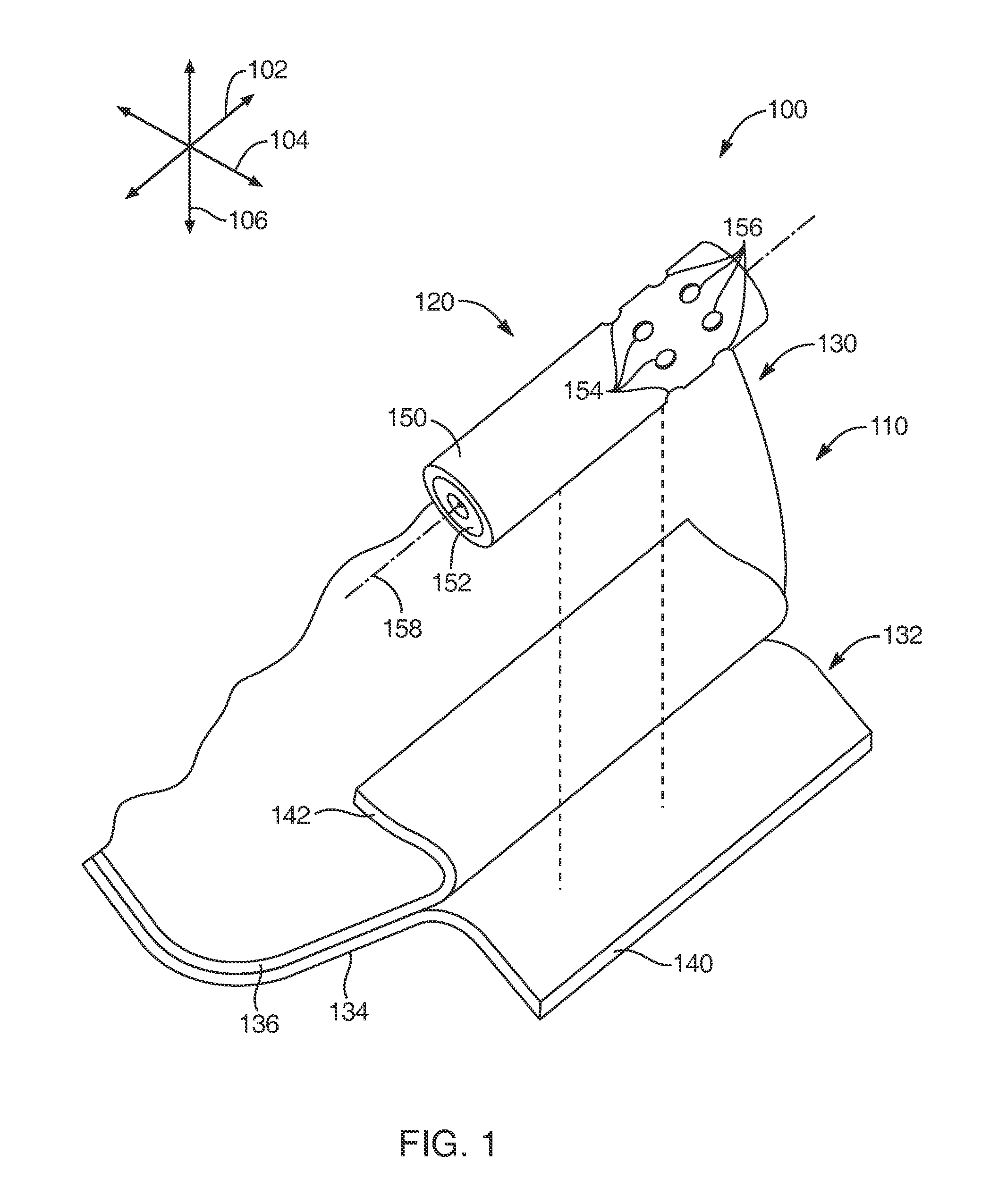
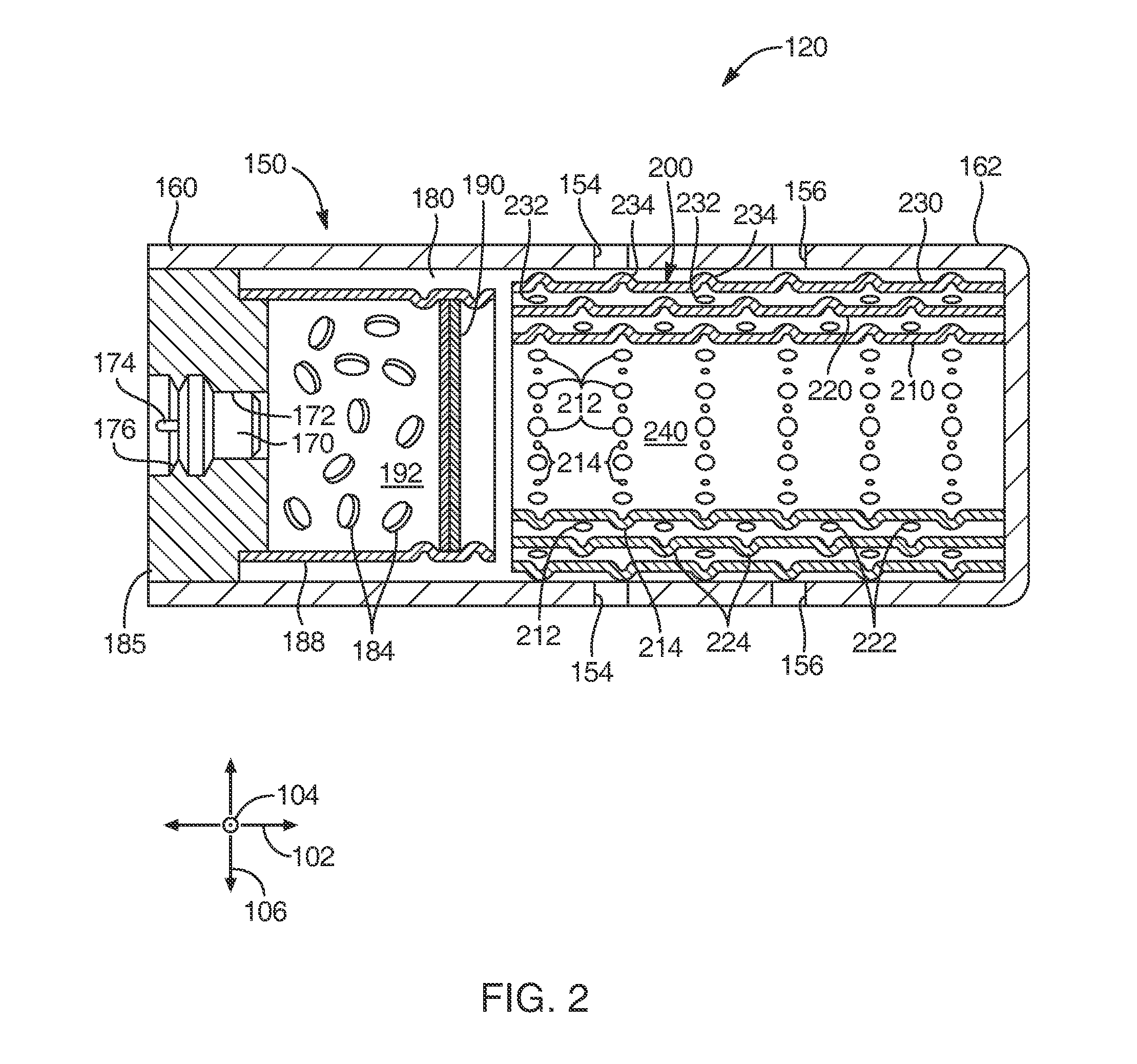
[0025]Exemplary embodiments of the present invention will be best understood by reference to the drawings, wherein like parts are designated by like numerals throughout. It will be readily understood that the components of the present invention, as generally described and illustrated in the Figures herein, could be arranged and designed in a wide variety of different configurations. Thus, the following more detailed description of exemplary embodiments of the apparatus, system, and method of the present invention, as represented in FIGS. 1 through 4, is not intended to limit the scope of the invention, as claimed, but is merely representative of exemplary embodiments of the invention.

[0026]The phrases “connected to,”“coupled to” and “in communication with” refer to any form of interaction between two or more entities, including mechanical, electrical, magnetic, electromagnetic, fluid, and thermal interaction. Two components may be coupled to each other even though they are not in di...


PUM

PropertyMeasurementUnit
Lengthaaaaaaaaaa
Shapeaaaaaaaaaa

Abstract

An airbag assembly may include an airbag and an inflator that provides inflation gas to inflate the airbag. A filter module may be positioned such that inflation gas exiting the inflator must first pass through the filter module. The filter module may be formed of a sheet of metal that is wrapped into a generally tubular shape. The filter module may have a first layer and a second layer that generally encircles the first layer. The first layer may have a pattern of holes and dimples that are separate from and / or displaced from each other. The dimples may protrude toward the second layer to maintain spacing to enable relatively unrestricted gas flow from the holes of the first layer through unaligned holes of the second layer. The resulting tortuous gas flow path may help to slow, cool, and / or purify the gas before it exits the inflator.

Description

TECHNICAL FIELD[0001]The present invention relates to automotive safety. More specifically, the present invention relates to airbag inflators that enhance the cost-effectiveness of airbag systems.BACKGROUND[0002]Inflatable safety restraint devices, or airbags, are mandatory on most new vehicles. Airbags are typically installed as part of a system with an airbag module in the steering wheel on the driver's side of car and in the dashboard on the passenger side of a car. In the event of an accident, a sensor within the vehicle measures abnormal deceleration and triggers the ignition of a charge contained within an inflator. Expanding gases from the charge fill the airbags, which immediately inflate in front of the driver and passenger to protect them from harmful impact with the interior of the car. Typically, airbags are concealed within the vehicle trim to be invisible during normal vehicle operation. In addition to the driver's side and passenger's side airbags, many vehicles also ...

Claims


Application Information

Patent Timeline
IPC IPC(8): B60R21/26
CPCB60R2021/26011B60R21/26B01D2279/10Y10T29/49604B01D39/10B01D46/2403
Inventor CLARK, MARCUS T.
Owner AUTOLIV ASP INC
Learn More