Diffractive optical element and measuring method

a technology of optical elements and measuring methods, applied in the direction of optical apparatus testing, reflection surface testing, instruments, etc., can solve the problem that the measurement accuracy with which these parameters can be determined using measuring instruments known from the prior art cannot meet the continuously increasing demands, and achieve the effect of improving accuracy

Inactive Publication Date: 2015-07-16
CARL ZEISS SMT GMBH
View PDF6 Cites 15 Cited by
  • Summary
  • Abstract
  • Description
  • Claims
  • Application Information

AI Technical Summary

Benefits of technology

The technical effect of this patent is that it provides a way to measure optical surfaces more accurately, even if they are non-symmetrical or have no rotationally symmetrical shapes. This can be useful in designing new lens systems or improving existing ones.

Problems solved by technology

The technical problem addressed in this patent is how to improve the accuracy of measurements made through a diffractive optical element's actual shape compared to its designed or intended shape. More specifically, the issue involves improving the precision of the computed grating pattern used in creating the diffractive structure of the optical element, including understanding any distortions or variations in the positioning of the gratings within the overall pattern. Current methods may require high costs and increased complexity, thus requiring improved efficiency and accuracy in identifying and addressing potential issues during manufacturing processes.

Method used


Image

  • Diffractive optical element and measuring method
  • Diffractive optical element and measuring method
  • Diffractive optical element and measuring method

Examples


Embodiment Construction

[0079]In the exemplary embodiments or embodiments described below, elements which are functionally or structurally similar to one another are as far as possible provided with the same or similar reference signs. Therefore, for understanding the features of the individual elements of a specific exemplary embodiment, reference should be made to the description of other exemplary embodiments or the general description of the invention.

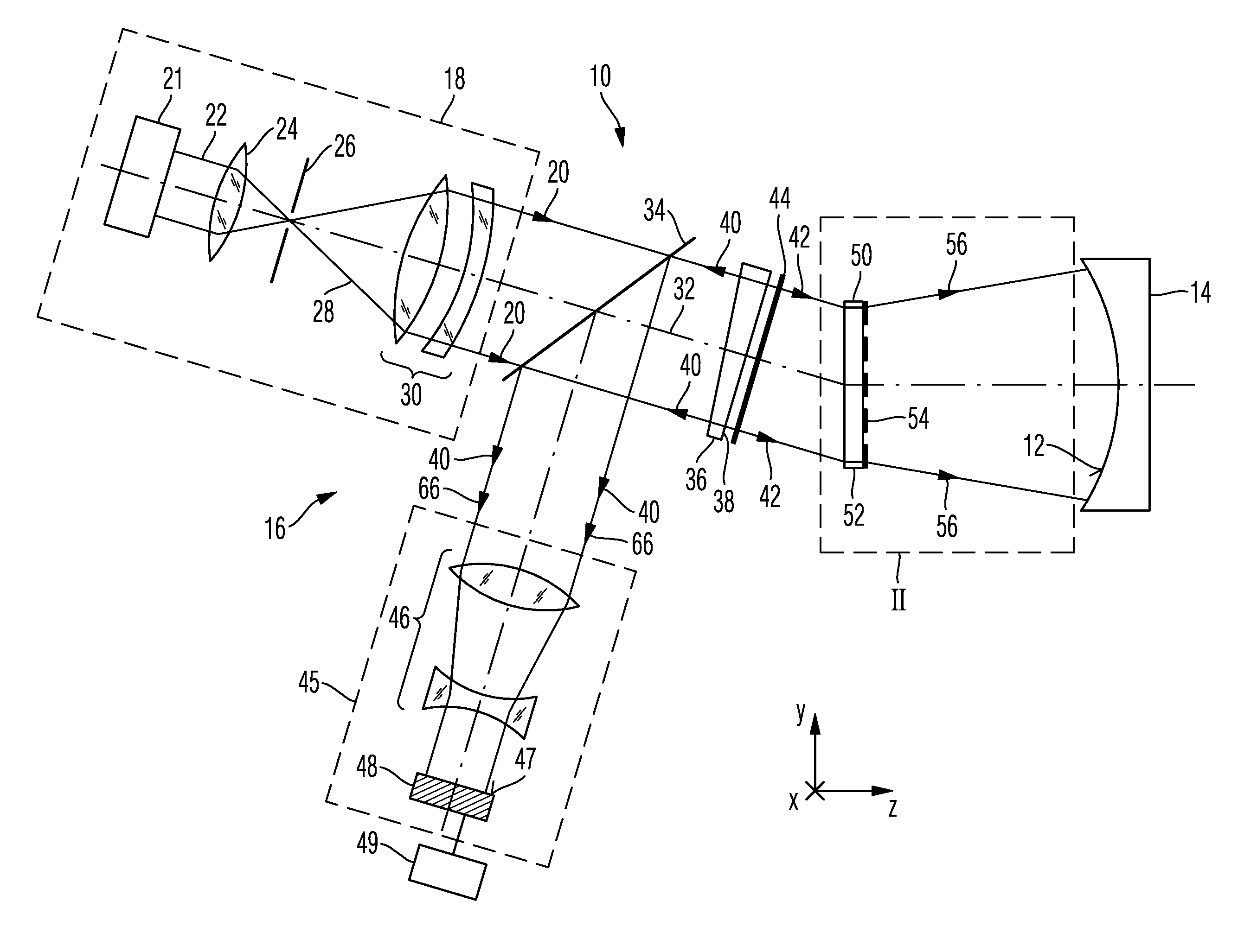
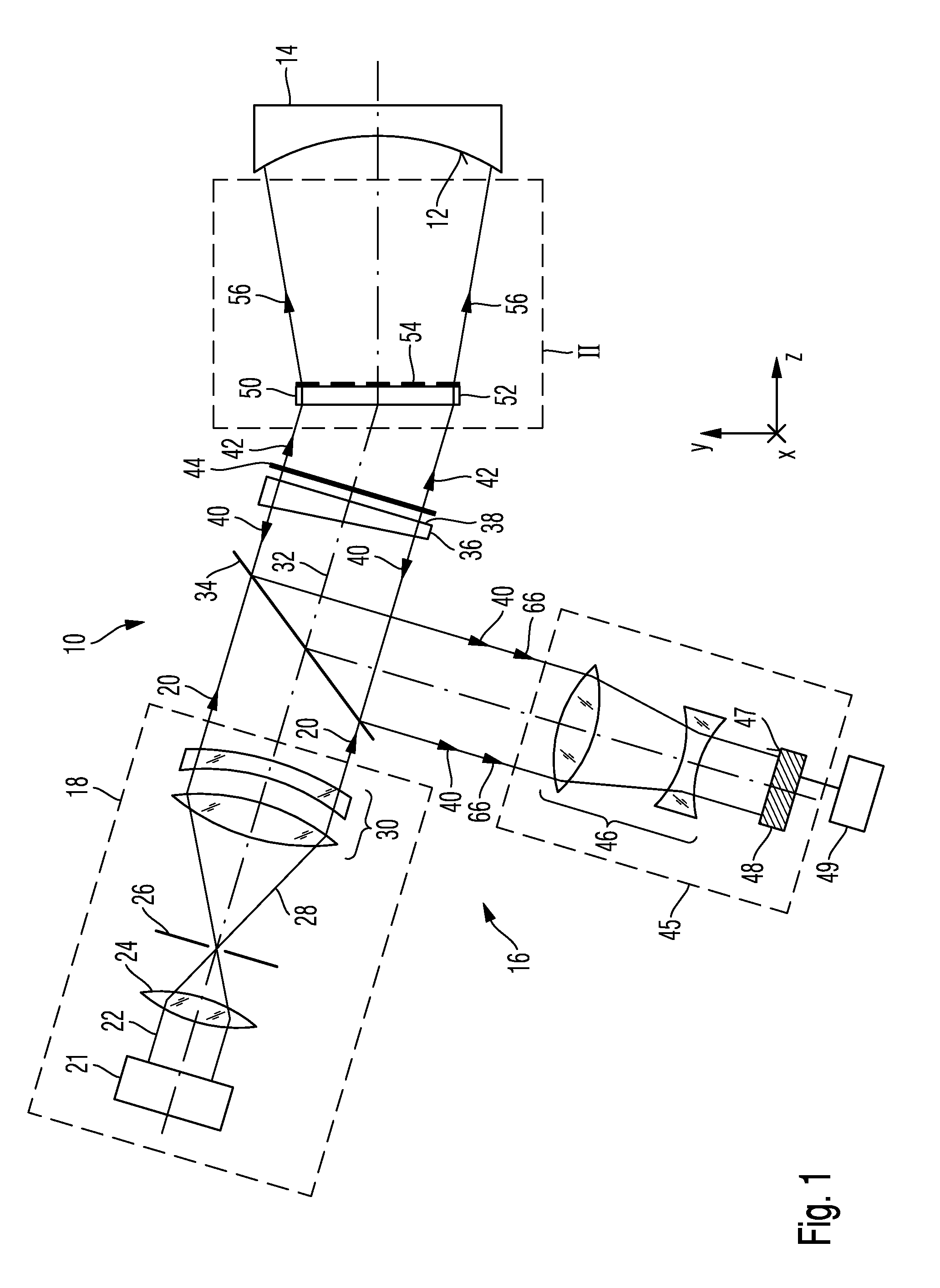
[0080]To facilitate the description, a Cartesian xyz-coordinate system is indicated in the drawing, which system reveals the respective positional relationship of the components illustrated in the figures. In FIG. 1, the x-direction extends perpendicularly to the plane of the drawing and into the latter, the y-direction extends upward and the z-direction extends toward the right.

[0081]FIG. 1 depicts an interferometric measurement system 10 in one embodiment according to the invention. The measurement system 10 is suitable for determining a deviation of an...


PUM

PropertyMeasurementUnit
Lengthaaaaaaaaaa
Fractionaaaaaaaaaa
Angleaaaaaaaaaa

Abstract

A diffractive optical element (50) with a substrate (52) and a diffractive structure pattern (54) arranged thereon. The diffractive structure pattern is configured to convert a plane or spherical input wave (42) radiated thereon into at least four separate output waves, wherein at least one of the output waves is a non-spherical wave (56), at least a further one of the output waves is a spherical wave (58; 70) and at least two further ones of the output waves respectively are a plane wave (60) or a spherical wave (72, 74).

Description


Claims


Application Information

Patent Timeline
Owner CARL ZEISS SMT GMBH
Why Eureka
Try Eureka