Sensor device

a sensor device and sensor technology, applied in the direction of measurement devices, magnetic field magnitude/direction magnetic field measurement using galvano-magnetic devices, etc., can solve the problem of high failure safety of module-like sensor devices

Active Publication Date: 2015-07-16
TDK MICRONAS GMBH
View PDF8 Cites 14 Cited by
  • Summary
  • Abstract
  • Description
  • Claims
  • Application Information

AI Technical Summary

Benefits of technology

[0010]In another embodiment, the first housing and the second housing have substantially or exactly the same the same outer dimensions. In particular, the outer dimensions of the first housing preferably do not differ from the outer dimensions of the second housing or differ at most preferably exclusively by the formations for a joining. In another preferred embodiment, catches and/or projections are formed on the first housing and/or on the second housing in order to join the first housing with the second housing simply and cost-effectively. In another embodiment, fixing device is provided, whereby the fixing device is formed rod-shaped and each of the fixing device has a catch at a head end or at both head ends, so that one of the fixing device is formed clamp-like. It is preferred to form the fixing device separately, so that the first housing is connected force-fittingly to the second housing by means of the clamp-shaped fixing device. In another embodiment, it is preferable to provide projections on both housings, so that in the joined state the fixing device and/or at least the catches of the fixing device are integrated into the housing and form a positive fit. It is preferred furthermore t

Problems solved by technology

As a result, the module-like senso

Method used


Image

  • Sensor device
  • Sensor device
  • Sensor device

Examples


first embodiment

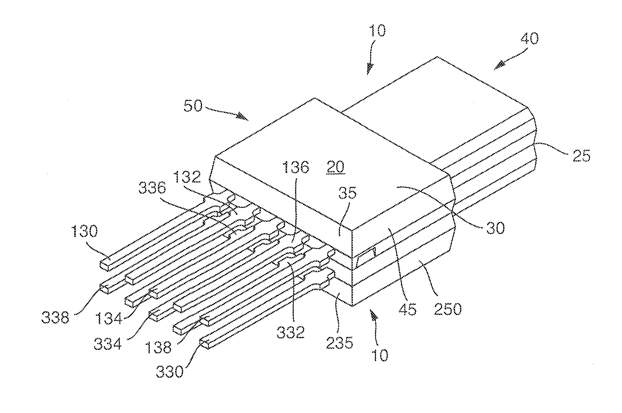
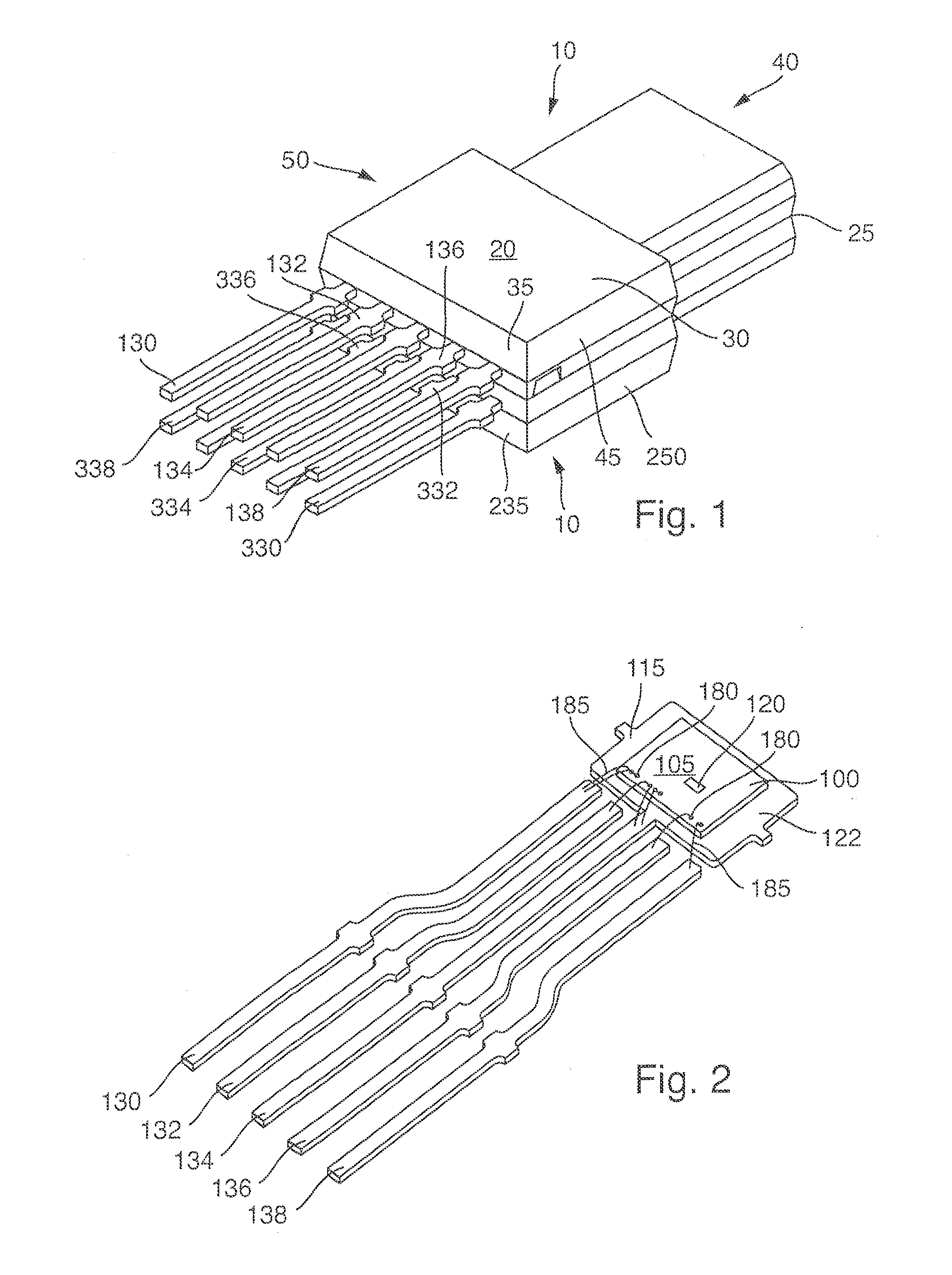
[0026]The illustration in FIG. 1 shows a view of the invention of a sensor device 10 formed as a module, having a first housing 20 and a second housing 220. It is understood that the outer dimensions of first housing 20 are preferably substantially identical, most preferably exactly identical to the outer dimensions of second housing 220. In the present case, two housings 20 and 220 are joined to form the module.

[0027]First housing 20 has a bottom side 25 and a top side 30. A face side 35 and a back side 40 and a first side surface 45 and a second side surface 50 are arranged between top side 30 and bottom side 25. Further, second housing 220 has a bottom side 225 and a top side 230. A face side 235 and a back side 240 and a first side surface 245 and a second side surface 250 are arranged between top side 230 and bottom side 225. In the present case, back side 40 of first housing 20 is connected force-fittingly to back side 240 of second housing 220 to form a module.

[0028]Stepped f...

second embodiment

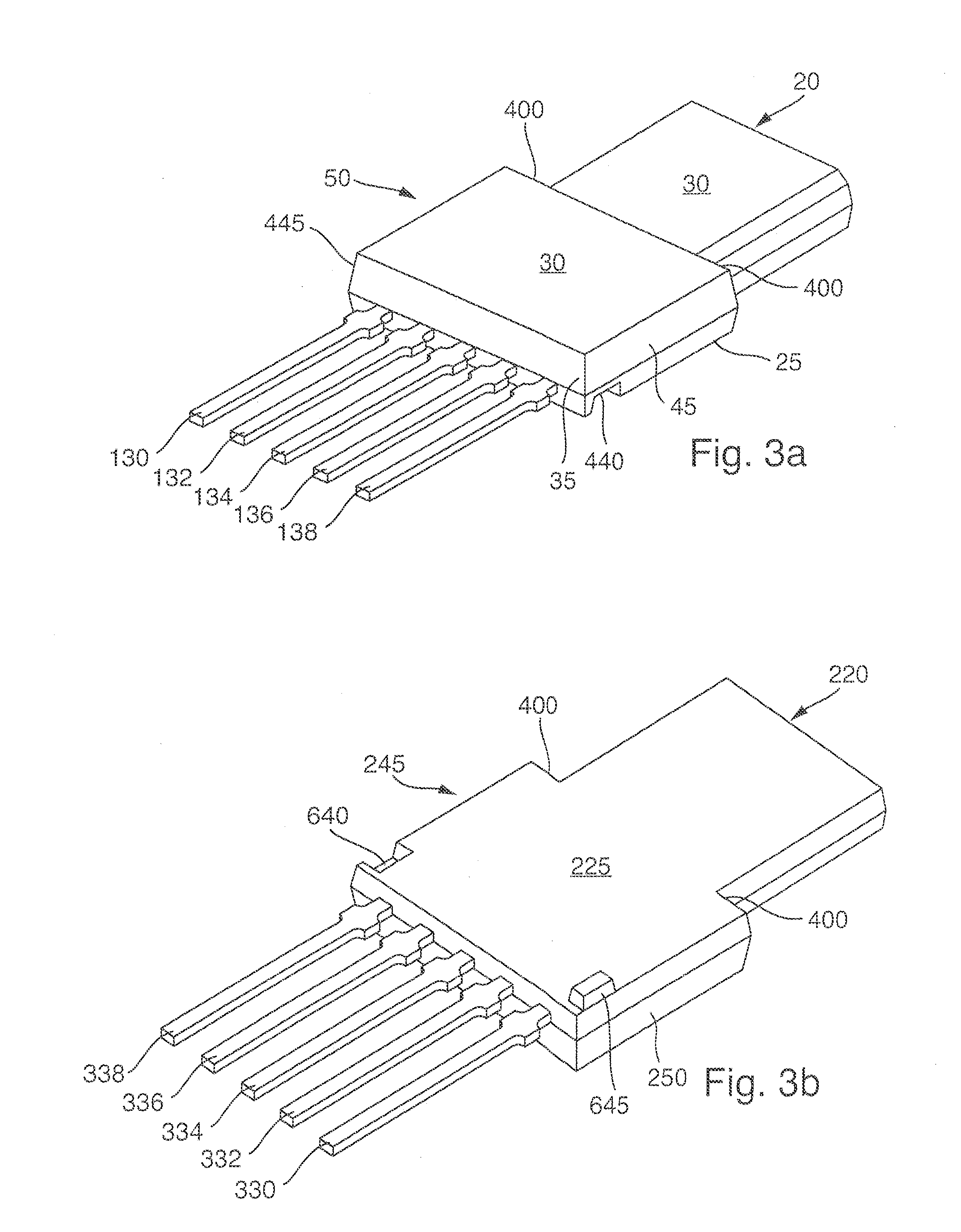
[0040]In the illustration of FIG. 5, a perspective view of the first housing and second housing are shown in which bottom side of the first housing is joined to the top side of the second housing. Only the differences relative to the illustration of the previous figures will be explained below. Rectangular elevations and depressions 740, 745, 840, and 845, arranged on the respective bottom sides 25 and 225 of first housing 20 and of second housing 220. On the respective top sides 30 and 230 rectangular depressions 940 and 945 are arranged. During the joining process the rectangular elevations 740 and 745 engage form-fittingly with the rectangular depressions 940 and 945 and form a centering aid, so that the two housings 20 and 220 are positioned precisely one over the other. Stepped formations 400 are formed in each case only on both side surfaces 45 and 50 of first housing 20 and on both side surfaces 245 and 250 of second housing 220. As a result, the module has larger outer dimen...


PUM


Abstract

A sensor device having a first housing with a first semiconductor body and a plurality of metallic terminal contacts for electrical contacting of a first sensor, and a second housing with a second semiconductor body with a plurality of metallic terminal contacts for electrical contacting of a second sensor. A section of the plurality of terminal contacts penetrates the second housing on the face side and the second semiconductor body is arranged with a back surface on a front side of the second metal substrate. The two housings form a module, whereby the two housings are connected form-fittingly to one another in the shape of a stack by a fixing device in a way in which the bottom side of the first housing is joined to the bottom side of the second housing and the plurality of terminal contacts of the two housings point in the same direction.

Description

[0001]This nonprovisional application claims priority under 35 U.S.C. §119(a) to European Patent Application No. 14000112.4-1560, which was filed in Europe on Jan. 13, 2014, and which is herein incorporated by reference.BACKGROUND OF THE INVENTION[0002]1. Field of the Invention[0003]The invention relates to a sensor device.[0004]2. Description of the Background Art[0005]DE 10 2010 030 801 A1 discloses integrated sensors, particularly Hall sensors, which are used, inter alia, for determining rotation angles for drive shafts. Furthermore, U.S. Pat. No. 5,644,473 and JP 3-32050 disclose stackable housings for IC.SUMMARY OF THE INVENTION[0006]It is therefore an object of the invention to provide a device that refines the conventional art. The object is attained by a sensor device according to the present invention.[0007]According to an embodiment of the invention, a sensor device is provided, having a first housing with a bottom side and a top side and a face side and a back side and a ...

Claims


Application Information

Patent Timeline
IPC IPC(8): G01R33/07G01R33/00G01R33/09
CPCG01R33/077G01R33/0094G01R33/09G01R33/0047
Inventor PILLA, CAMILLO
Owner TDK MICRONAS GMBH
Why Eureka
Try Eureka