Rotatable camera device

a camera device and rotor technology, applied in the field of rotatable camera devices, can solve the problems of users usually suffering from failures, inconvenient device mounting, and difficulty in rotating the camera, and achieve the effects of easy and rapid mounting on a wall, ceiling or a surface of an object, and low requirements for a place for mounting a camera devi

Inactive Publication Date: 2015-07-16
BESEYE CLOUD SECURITY
View PDF18 Cites 11 Cited by
  • Summary
  • Abstract
  • Description
  • Claims
  • Application Information

AI Technical Summary

Benefits of technology

[0010]In another embodiment, a heavy unit is configured in the base for stabilizing the base and the body. The heavy unit also provides the ability as a buffer to balance the movements of the centroid during rotations, and therefore protect the body and the camera from collisions. Since electronic elements in camera are highly interfered and easily got wrecked by magnetic force, the neck places the camera a distance away from the first magnetic unit and the second magnetic unit to protect the camera from the magnetic forces.
[0011]In yet another embodiment, the camera device may further comprise a first fixing unit, connected onto the bottom of the base, and a second fixing unit. The second fixing unit comprises at least one first combining unit, and the first fixing unit comprises at least one second combining unit; wherein the at least one first combining unit is a mortise or a concave, and the at least one second combining unit is a tenon or a convex; or, on the contrary, the at least one first combining unit is a tenon or a convex, and the second combining unit is a mortise or a concave. The second fixing unit further comprises at least one fixing hole for fixing the second fixing unit onto a surface with nails or fixtures. The camera device is then able to be mounted onto the surface by combining the first combining unit and the second combining unit. In this embodiment, the camera device is able to be mounted onto a wall, a ceiling, or a surface of an object easily and rapidly. Besides, since sizes of the base and the second fixing unit are relative smaller, the requirements for a place for mounting a camera device are relative low.
[0012]The camera device in accordance with the present invention provides advantages such as easily adjusting the direction of camera to optimize the camera recording field, smoothly rotating the body without physical hindrances, fast mounting, and suitable for a variety of places under different situations.

Problems solved by technology

However, conventional camera devices in this field usually are manufactured with several connected arms and physical joints, which led to inconvenience during device mounting and difficulties in camera rotating.
Users usually suffer from failures when trying to adjust the camera to a specific position or angle, since the unsmooth surfaces and rectangular shapes of camera devices largely restrict the camera device from movements.
These situations are encountered intensively when attempting to mount the camera device to places such as wall, ceiling, or corner.
The physical features of camera devices by conventional camera devices largely refrain users from convenience and ease, since the complexities in arms and joints require an enormous amount of time to build a camera system.
Besides, since sizes of the base and the second fixing unit are relative smaller, the requirements for a place for mounting a camera device are relative low.

Method used


Image

  • Rotatable camera device
  • Rotatable camera device
  • Rotatable camera device

Examples


Embodiment Construction

[0023]In a general aspect, at least one embodiment in accordance with the present invention relates to a camera device. More particularly, at least one embodiment relates to an internet protocol camera supporting a wide range of rotation. The embodiments and drawings provided here show different aspects of the present invention. However, the present invention are neither limited to any embodiment nor drawing thereof.

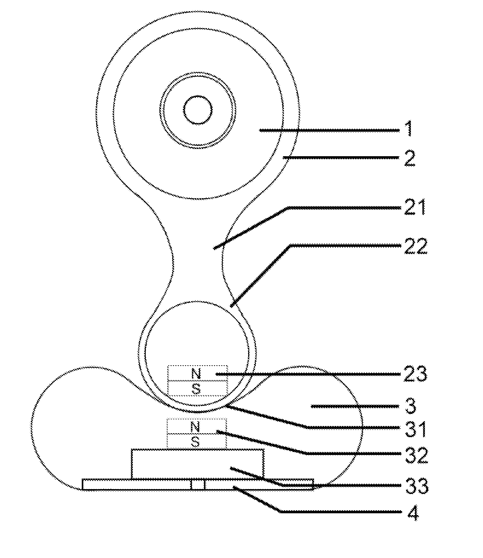
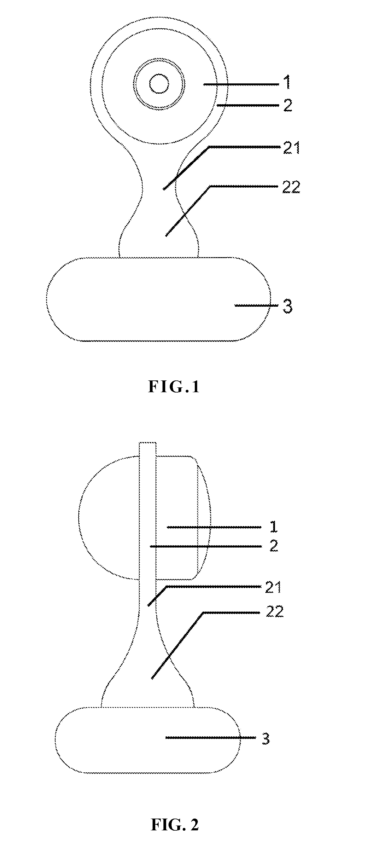
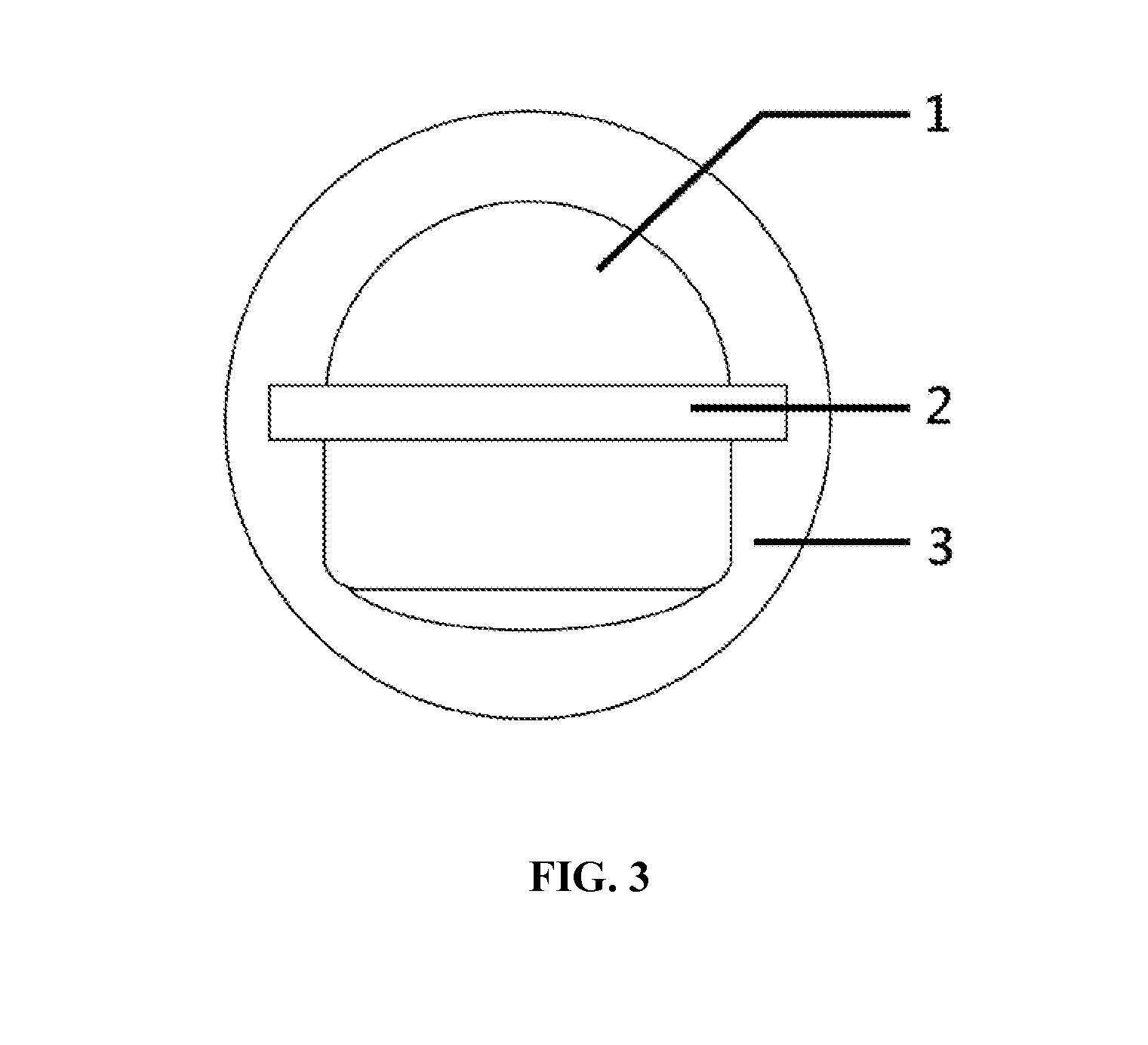
[0024]FIGS. 1-3 represents an embodiment in accordance with the present invention. FIG. 1 illustrates a front plan view of the embodiment; FIG. 2 illustrates a side plan view of the embodiment; and, FIG. 3 illustrates a top plan view of one embodiment. In this embodiment, the camera device comprises a camera 1, a body 2, a neck 21, a spherical unit 22 and a base 3. Wherein the camera 1 is configured onto the body 2; and, the neck 21 of the body 2 is configured in-between the spherical unit 22 and the camera 1 to support the camera 1. The spherical unit 22 is then placed ...


PUM


Abstract

The present invention relates to a camera device, wherein the camera device comprising a base with a fillister; a body with a spherical unit and a neck; and a camera configured onto the body. The spherical unit fits the fillister to form a joint allowing a wide range of rotation in all direction. The base further comprises a first fixing unit and a second fixing unit. Therefore, the camera device is able to be easily mounted onto a targeted surface; and, the camera field of view is able to be rapidly optimized toward a specific direction.

Description

BACKGROUND OF THE INVENTION[0001]1. Technical Field[0002]At least one disclosed embodiment in accordance with the present invention relates to a camera device. More particularly, at least one disclosed embodiment relates to an internet protocol camera supporting a wide range of rotation.[0003]2. Description of the Related Art[0004]Recently, camera device has been applied intensively to various circumstances including observing crime hotspots, monitoring children or senior citizens, and establishing video links. Camera therefore largely increases convenience and security nowadays.[0005]However, conventional camera devices in this field usually are manufactured with several connected arms and physical joints, which led to inconvenience during device mounting and difficulties in camera rotating. Users usually suffer from failures when trying to adjust the camera to a specific position or angle, since the unsmooth surfaces and rectangular shapes of camera devices largely restrict the ca...

Claims


Application Information

Patent Timeline
Patent Type & Authority Applications(United States)
IPC IPC(8): G03B17/56
CPCG03B17/561F16M11/041F16M11/14F16M13/00F16M13/02F16M2200/041G08B13/19619G08B13/1963
Inventor CHANG, TSE-MINGTSAI, PEI-YUNTU, CHENG-HAN
Owner BESEYE CLOUD SECURITY
Why Eureka
Try Eureka