
3D design and fabrication system for implants

a 3d design and implant technology, applied in the field of fabricating aesthetic and reconstructive surgical implants, can solve the problems of tedious and inaccurate, large number of implants available that are not specifically tailored, and high cost of mri and ct scans

Active Publication Date: 2015-07-16
KOTLUS BRETT
View PDF2 Cites 18 Cited by
  • Summary
  • Abstract
  • Description
  • Claims
  • Application Information

AI Technical Summary

Benefits of technology

The present patent is about a method of designing, presenting, generating, and fabricating custom implants. It involves obtaining a 3D image of a site to receive an implant, simulating volumetric changes of the site, generating a virtual 3D implant that effects the volumetric changes, and fabricating a real 3D implant that includes the volumetric changes. The invention also provides a method of correcting disfigurement in a patient, replacing a disc in a patient's back, and using this method to fabricate an implant. The technical effects are that it allows for the creation of custom implants that can be tailored to a patient's unique needs, resulting in improved outcomes and patient satisfaction.

Problems solved by technology

In other words, the majority of implants available are not specifically tailored to a patient and do not take normal asymmetry or other unique qualities into account.
Patients receive radiation from CT scans and both MRI and CT scans are quite expensive to perform.
They can be unshaped materials (blocks) that are carved by hand, which is tedious and inaccurate.
They do not allow for visualization of a simulated surgical outcome.
Also, they do not allow for customization with virtual 3D external photographs.
They do not visually predict the soft tissue modifications that will occur after implantation.

Method used


Image

  • 3D design and fabrication system for implants
  • 3D design and fabrication system for implants
  • 3D design and fabrication system for implants

Examples


Embodiment Construction

[0024]The present invention is generally directed to a method of designing, presenting, generating, and fabricating custom implants, preferably for use in humans, based on 3D imaging. The customization is based on individual anatomic findings, taking into account pre-existing asymmetries, unique structures, and desired modifications, thus obviating the need for generic implants. The method allows for visualization of a virtual implant's external appearance (i.e. how the implant will appear from the outside when implanted under the body tissues) before implantation takes place. The method is also dictated by the desired appearance, fit, and function of the virtual implant.

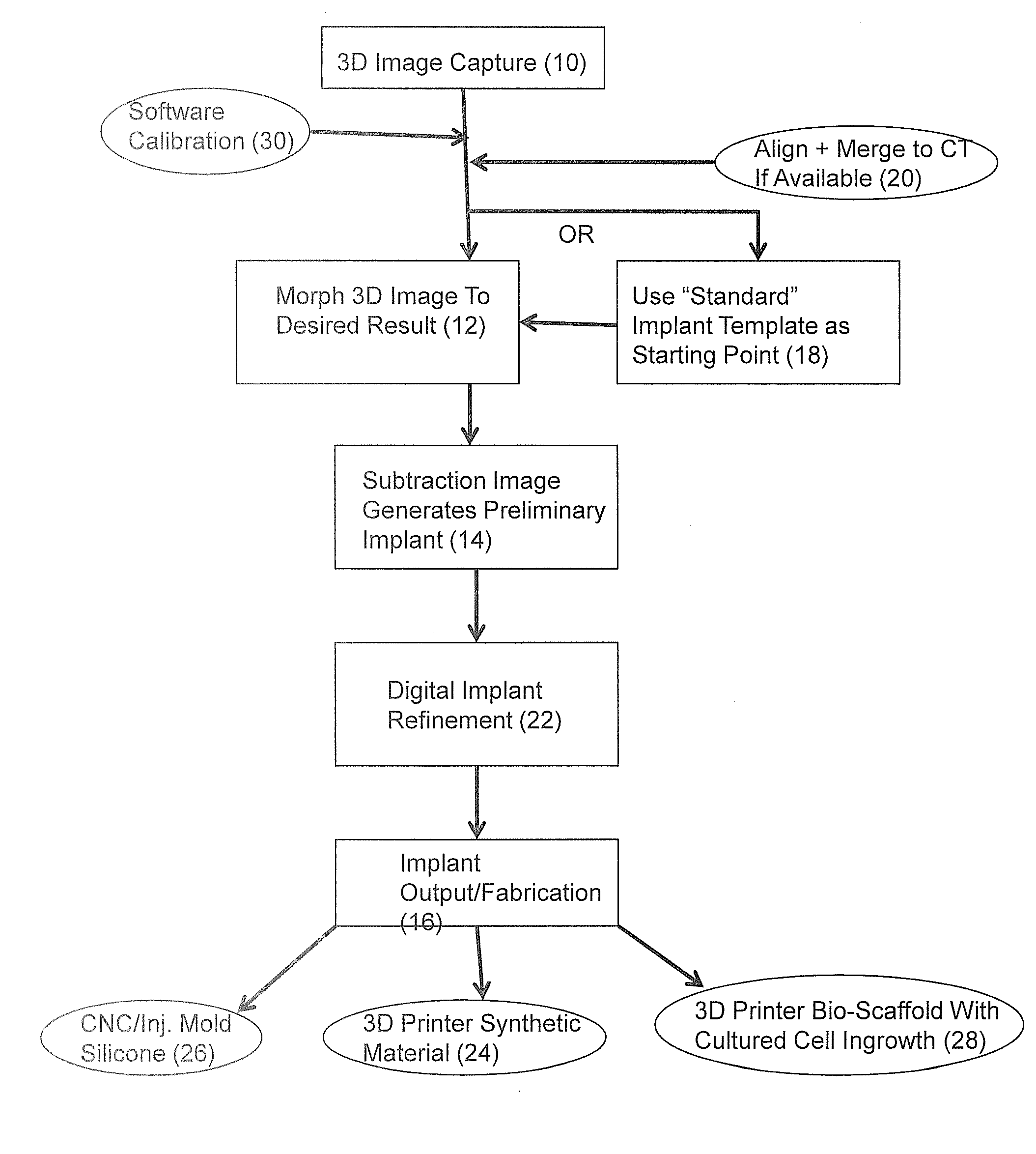
[0025]More specifically, the method includes obtaining an external 3D image of a site or area of the body to receive an implant 10, simulating volumetric changes of the site 12, generating a virtual 3D implant 14 that effects the volumetric changes of the site, and fabricating a real 3D implant 16 that includes the ...


PUM

PropertyMeasurementUnit
shapeaaaaaaaaaa
CT scanaaaaaaaaaa
MRIaaaaaaaaaa

Abstract

A method of designing, presenting, generating, and fabricating custom implants by obtaining a 3D image of a site to receive an implant, simulating volumetric changes of the site, generating a virtual 3D implant that effects the volumetric changes of the site, and fabricating a real 3D implant that includes the volumetric changes. A method of designing, presenting, generating, and implanting custom implants by obtaining a three-dimensional (3D) image of a site to receive an implant, simulating volumetric changes of the site, generating a virtual 3D implant that effects volumetric changes of the site, and injecting or infusing a gel or semi-solid implant into a patient to effect the volumetric changes. A method of implanting a custom implant in a patient. A method of correcting disfigurement in a patient. A method of replacing a disc in a patient's back. An implant fabricated by this method.

Description

BACKGROUND OF THE INVENTION[0001]1. Technical Field[0002]The present invention relates to methods of fabricating aesthetic and reconstructive surgical implants. More specifically, the present invention relates to methods of generating custom implants.[0003]2. Background Art[0004]After serious injury or disease, restoration of normal function, symmetry, and appearance can require surgery involving implanting materials to reshape the affected area of the body. Implants are also used to augment the shape and volume of normal anatomic regions of the body for aesthetic purposes. For the most part, commonly used implants are generic, pre-fabricated shapes and sizes that must be fit to each individual as best as they can. In other words, the majority of implants available are not specifically tailored to a patient and do not take normal asymmetry or other unique qualities into account.[0005]There are several methods of generating implants that are currently used. U.S. Pat. No. 7,747,305 to...

Claims


Application Information

Patent Timeline
Patent Type & Authority Applications(United States)
IPC IPC(8): G05B19/4097B29C67/00A61F2/44G06F17/50A61F2/00A61F2/30
CPCG05B19/4097A61F2/0059A61F2/30942A61F2/442G06F17/50A61F2002/444A61B2019/502A61B2019/507A61B2019/508A61F2002/30948B29C67/0088A61F2/44G06T19/20G06T2200/08G06T2219/2021Y10T29/49B29C64/112G16H50/50Y02P10/25B22F10/80G06F30/00
Inventor KOTLUS, BRETT
Owner KOTLUS BRETT
Learn More