Method and system for engine starting

Active Publication Date: 2015-07-23
FORD GLOBAL TECH LLC
View PDF3 Cites 10 Cited by
  • Summary
  • Abstract
  • Description
  • Claims
  • Application Information

AI Technical Summary

Benefits of technology

[0002]It may be desirable from a driver's standpoint to make an engine run-up to idle speed as soon as possible after the driver requests an engine start. On the other hand, running-up the engine to idle speed as fast as possible may increase engine emissions. Therefore, it may be desirable to provide an engine run-up that produc

Problems solved by technology

On the other hand, running-up the engine to idle speed as fast as possible may increase engine emissions.
However, injecting fuel to an arbitrary engine cylinder or all

Method used


Image

  • Method and system for engine starting
  • Method and system for engine starting
  • Method and system for engine starting

Examples


Embodiment Construction

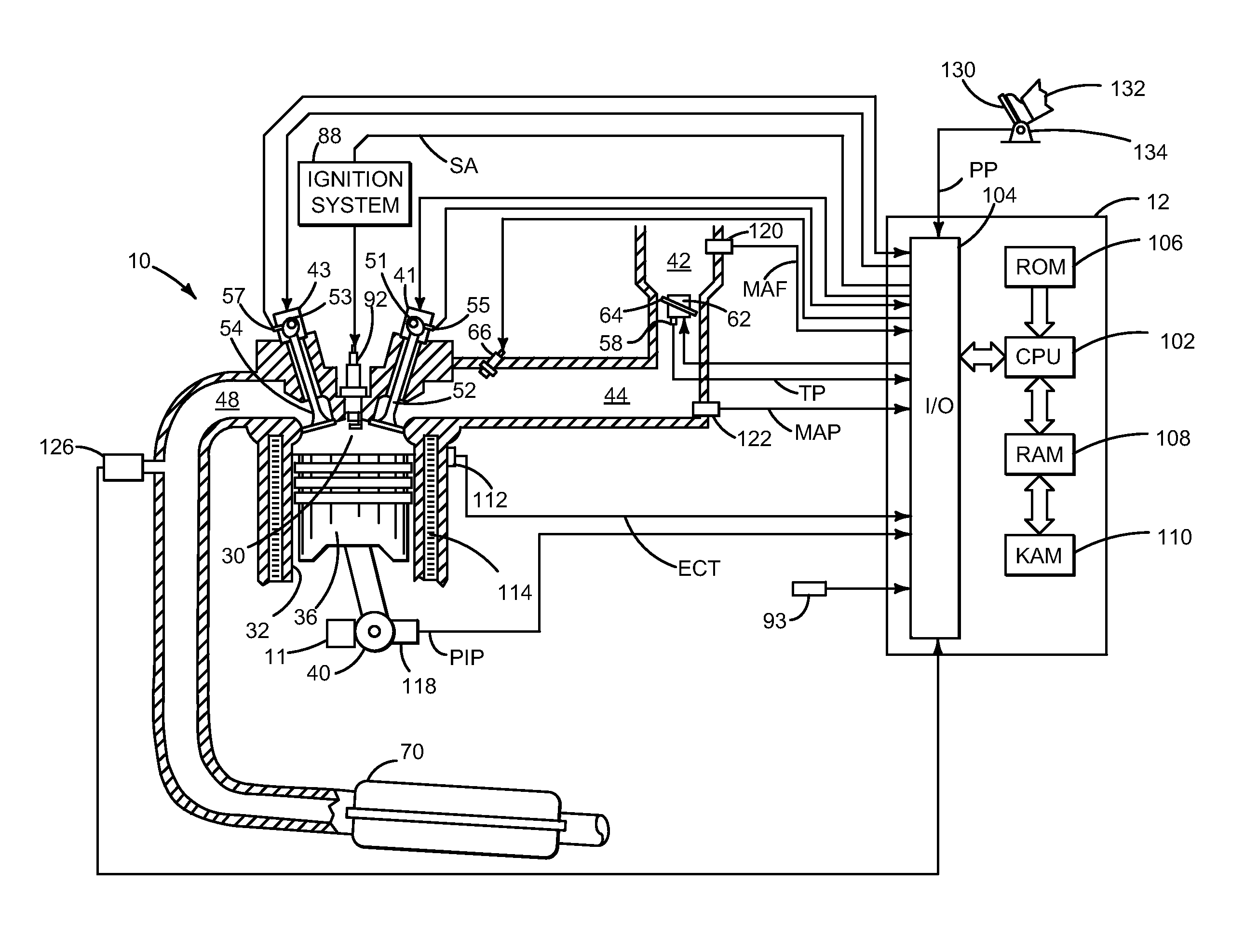
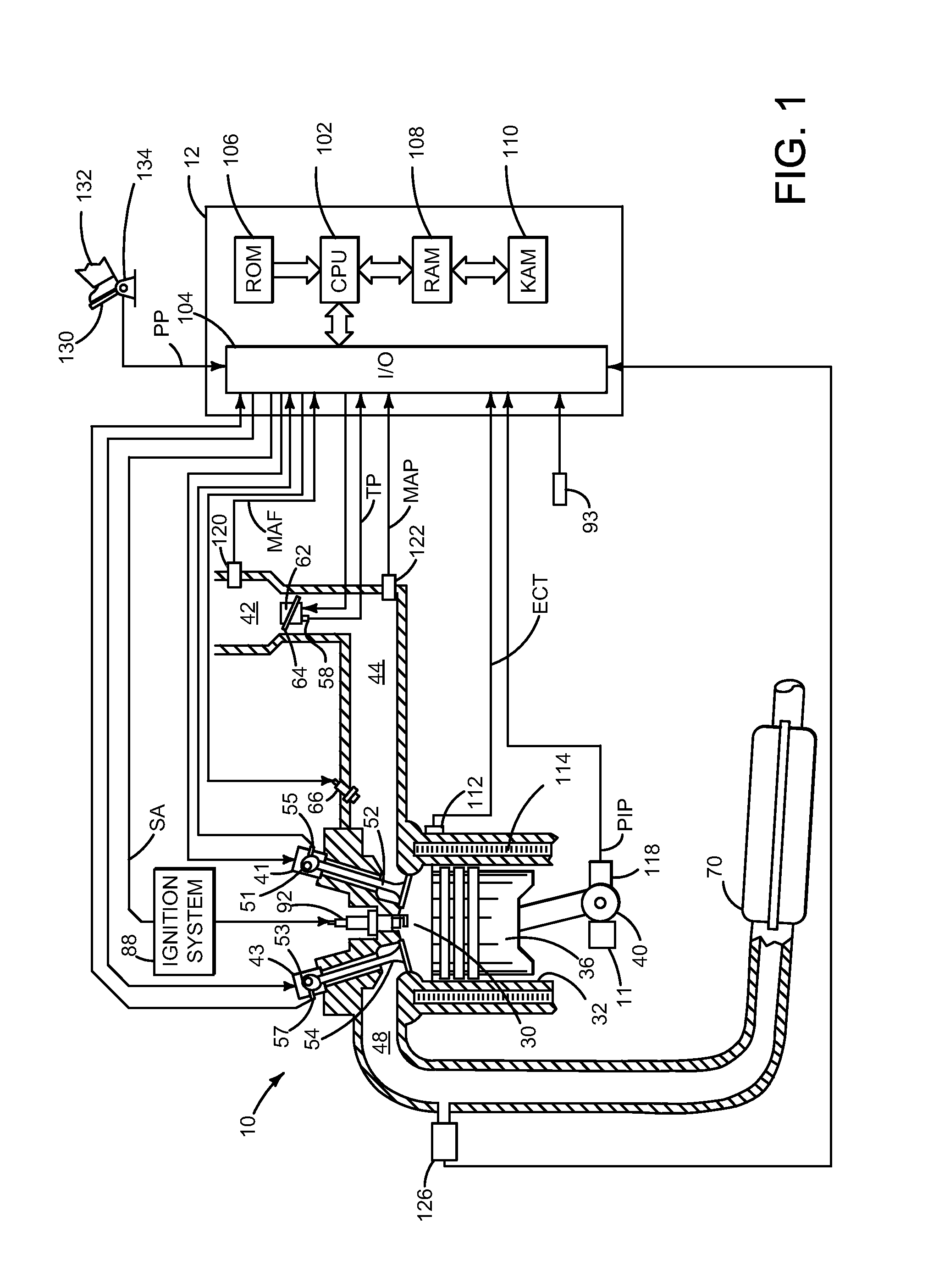
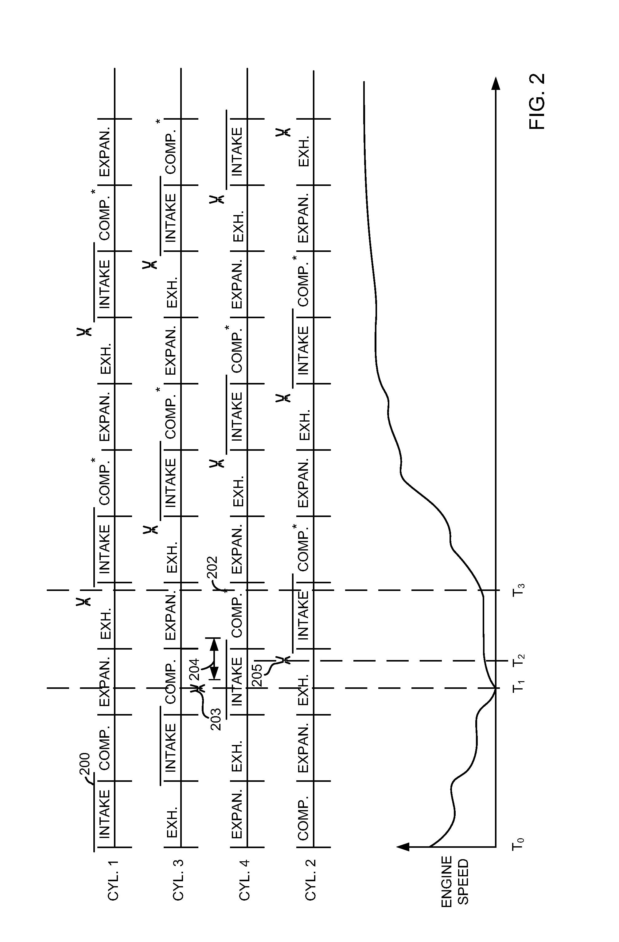
[0012]The present description is related to starting an engine. The methods described herein may be applied during warm or cold engine starts. Further, the methods and systems described herein are applicable to engines that operate solely on petrol, alcohol, or mixtures of petrol and alcohol. FIGS. 2 and 3 show example engine starting sequences according to the method described in FIG. 4. The method of FIG. 4 provides for beginning to inject fuel to a cylinder while the cylinder's intake valve is open.

[0013]Referring to FIG. 1, internal combustion engine 10, comprising a plurality of cylinders, one cylinder of which is shown in FIG. 1, is controlled by electronic engine controller 12. Engine 10 includes combustion chamber 30 and cylinder walls 32 with piston 36 positioned therein and connected to crankshaft 40. Starter motor 11 may selectively engage and rotate crankshaft 40 during engine starting. Combustion chamber 30 is shown communicating with intake manifold 44 and exhaust mani...


PUM


Abstract

A method and system for improving starting of an engine is presented. In one example, the method selects a first cylinder to receive fuel since engine stop based on intake valve closing time. The method also describes selecting the first cylinder to receive fuel since engine stop based on an end of fuel injection time.

Description

FIELD[0001]The present description relates to methods and systems for improving starting of an engine. The method may be particularly useful for engines that are operated using different types of fuels.BACKGROUND AND SUMMARY[0002]It may be desirable from a driver's standpoint to make an engine run-up to idle speed as soon as possible after the driver requests an engine start. On the other hand, running-up the engine to idle speed as fast as possible may increase engine emissions. Therefore, it may be desirable to provide an engine run-up that produces low emissions while at the same time not extending the run-up time so as to disappoint the driver. However, injecting fuel to an arbitrary engine cylinder or all engine cylinders at the same time may provide somewhat desirable engine starting results at times while producing disappointing engine starting results at other times.[0003]The inventors herein have recognized the above-mentioned disadvantages and have developed a method for s...

Claims


Application Information

Patent Timeline
IPC IPC(8): F02D41/30
CPCF02D41/30F02D41/042F02D41/0025F02D2041/0092F02D41/062F02M61/145
Inventor GIBSON, ALEXANDER O'CONNORWOOLDRIDGE, STEVENREICHE, DAVID BRUCEVANDERWEGE, BRAD ALANSANBORN, ETHAN D.
Owner FORD GLOBAL TECH LLC
Why Eureka
Try Eureka