Controlling cylinder mixture and turbocharger operation

a technology of cylinder mixture and turbocharger, which is applied in electrical control, non-mechanical valves, instruments, etc., can solve the problems of affecting the amount of exhaust gas residuals, affecting the operation of turbocharger and cylinder, and less available space for fresh air in the cylinder, so as to reduce the variation of cylinder mixture, reduce the difference in mixture differences and flow differences between different cylinder groups of turbocharged engines, and reduce the effect of cylinder mixture variation

Active Publication Date: 2011-07-26
FORD GLOBAL TECH LLC
View PDF26 Cites 21 Cited by
  • Summary
  • Abstract
  • Description
  • Claims
  • Application Information

AI Technical Summary

Benefits of technology

[0007]Variable valve operation provides an additional degree of freedom to equalize cylinder mixtures and balance mass flow through different cylinder groups of a turbocharged engine. By adjusting valve timing relative to crankshaft position and / or by adjusting valve lift, mixture differences and flow differences between different cylinder groups of a turbocharged engine can be reduced. For example, a “V” engine having two cylinder groups and two turbochargers can have less cylinder mixture variation between cylinder banks when engine valve timing is used to equalize exhaust gas residuals between the cylinder banks. Specifically, valve timing can be used to adjust the exhaust gas residual amount and cylinder air charge at a given intake manifold pressure. Therefore, if one bank of a turbocharged cylinder experiences a different cylinder backpressure than the other cylinder bank, due to different waste gate positions of the two turbochargers for example, valve timing adjustments can be used to mitigate differences in exhaust gas residuals and cylinder charge mixtures between the cylinder banks.
[0008]In another aspect of the present description, engine valve adjustments can be made in conjunction with turbocharger waste gate or vane adjustments to equalize flow between compressors while also reducing variation of exhaust gas residuals between cylinder banks. In one example, the position of turbocharger waste gates and the valve timing of exhaust valves can be adjusted to regulate energy supplied to the turbines and exhaust gas residuals of an engine having two cylinder banks. If a compressor approaches a surge condition, its waste gate can be opened and exhaust valve timing retarded so that residuals are maintained at the same time that the amount of exhaust gas energy delivered to the turbocharger is lowered.
[0009]The present description may provide several advantages over prior systems and methods. Specifically, the present method can achieve desired cylinder mixtures while regulating turbocharger operation, at least during some conditions. Further, the method can improve engine emissions because cylinder exhaust gas residuals can be controlled even if there are exhaust backpressure differences between cylinder banks. In addition, the method can produce more uniform cylinder mixtures and provide torque that is more uniform or equal between engine cylinder banks or cylinders.
[0010]The present method also provides unexpected results. Specifically, the method makes it possible to make finer adjustments to the turbocharger compressor flow so that the compressor may be operated closer to the compressor surge region. This can extend the turbocharger operating envelope. Also, the method can improve turbocharger durability and reduce warranty because the possibility of entering surge conditions when regulating compressor flow at low flow conditions is reduced.

Problems solved by technology

For example, the method simply adjusts a turbocharger waste gate or variable geometry vane position, thereby simultaneously affecting turbocharger and cylinder operation.
In other words, adjusting the waste gate or vane position changes the exhaust backpressure and can affect the amount of exhaust gas residuals that are trapped in a cylinder since the exhaust backpressure acts to impede flow from the cylinder.
Further, when cylinder volume is displaced by additional residual exhaust gas, there is less available space for fresh air in the cylinder.
Consequently, cylinder charge air amount and cylinder charge residual amount may change in an undesirable manner when a waste gate or turbine vanes are adjusted to regulate a turbocharger.
As a result, regulation and / or control of a turbocharger may have undesirable effects on engine emissions, fuel consumption, performance, audible noise, and uniform cylinder torque production.

Method used


Image

  • Controlling cylinder mixture and turbocharger operation
  • Controlling cylinder mixture and turbocharger operation
  • Controlling cylinder mixture and turbocharger operation

Examples


Embodiment Construction

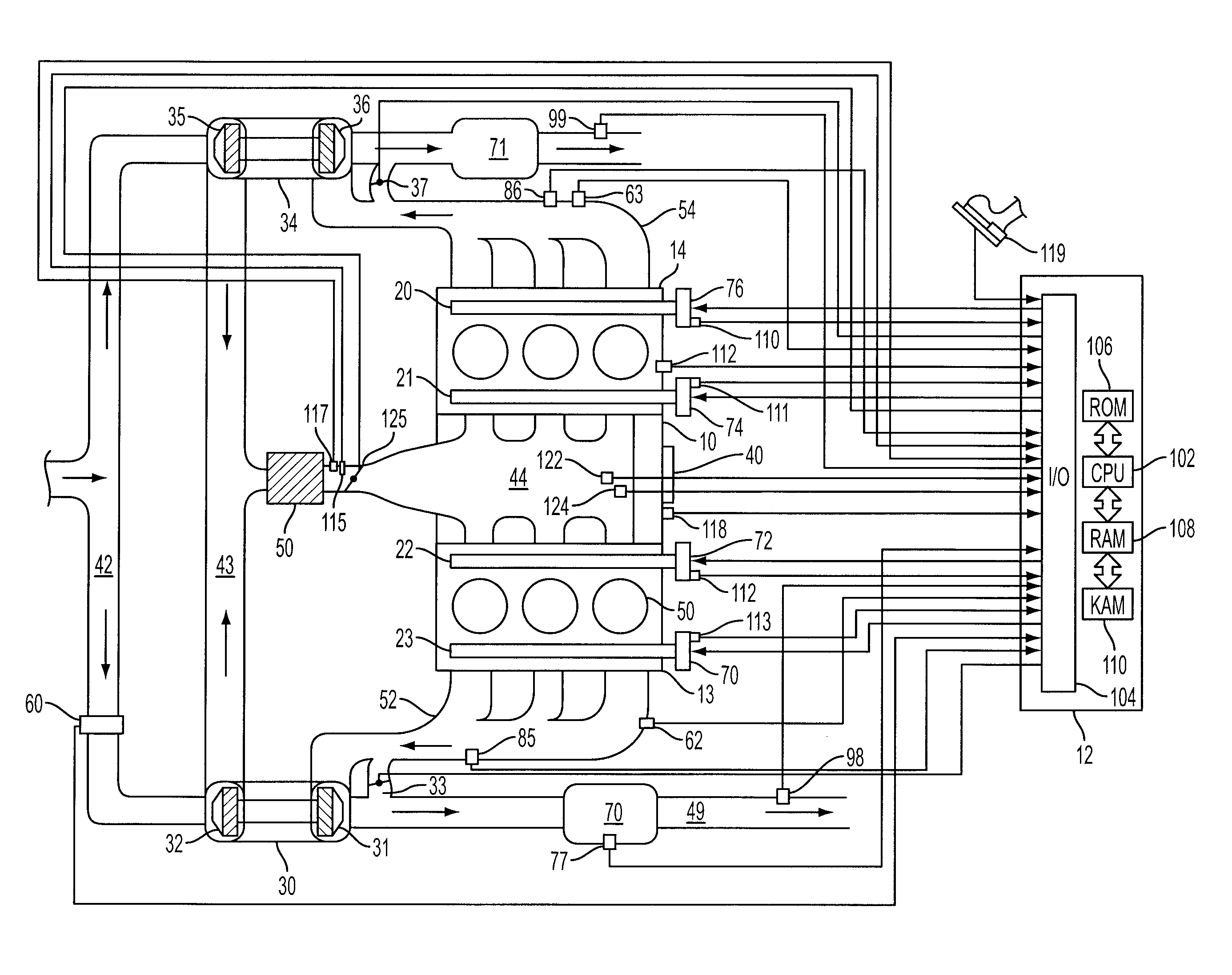
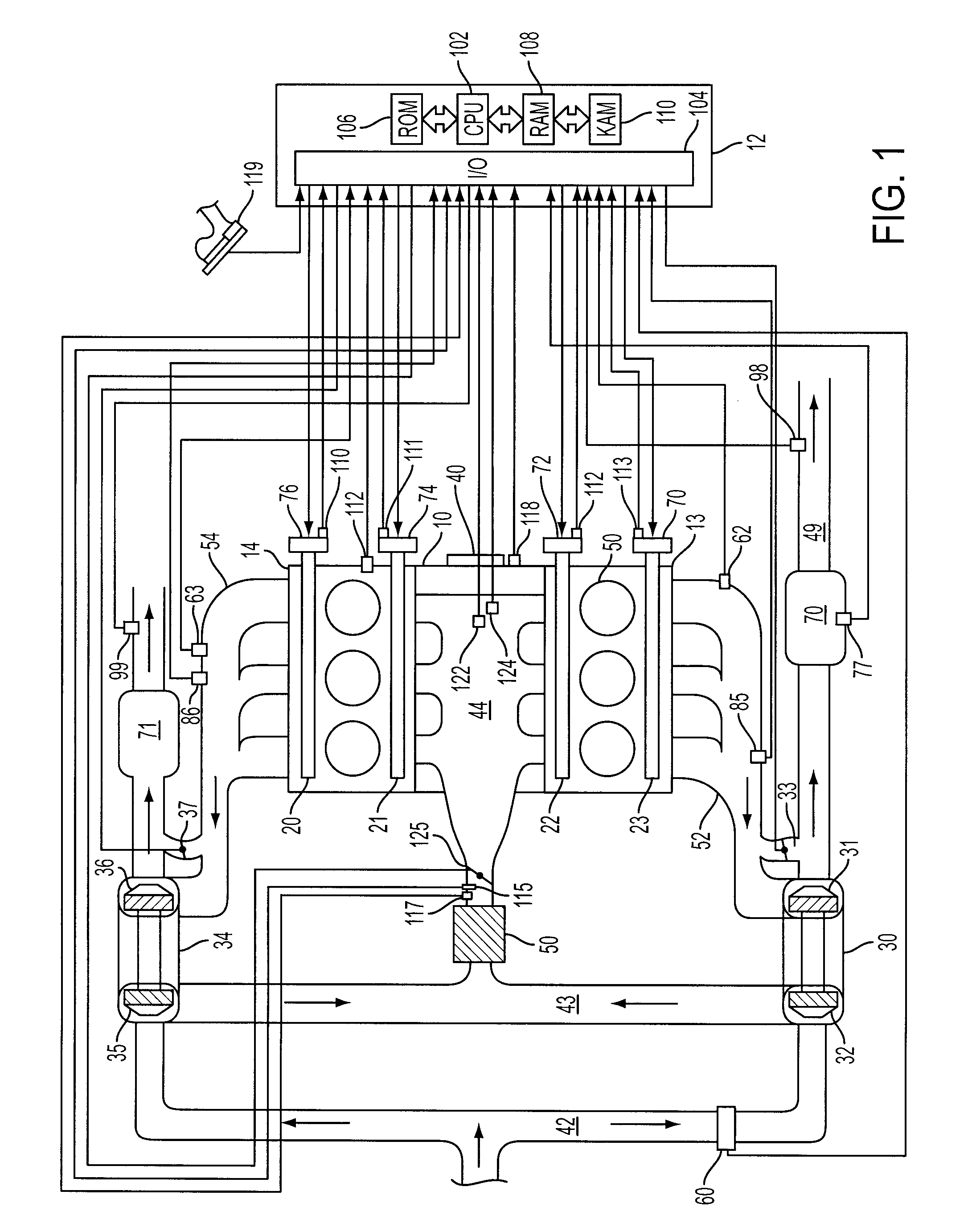
[0020]Referring to FIG. 1, internal combustion engine 10 is controlled by electronic engine controller 12. Engine 10 includes a plurality of cylinders in a “V” configuration that are similar to cylinder 50. Cylinder banks 13 and 14 are comprised of three cylinders each. Intake cams 21 and 22 operate intake valves (not shown) to regulate airflow into the cylinders of banks 13 and 14. Exhaust cams 20 and 23 operate exhaust valves (not shown) to regulate exhaust flow out of cylinder banks 13 and 14. Timing of intake and exhaust cams relative to crankshaft position can be varied by adjusting phasors 76, 74, 72, and 70. Alternatively, one or more intake, or exhaust valves may be operated without assistance from a mechanical cam (e.g., electrically or hydraulically actuated valves). Further, intake and / or exhaust valves may be configured to vary valve lift. Each cylinder surrounds a piston that transfers combustion energy to mechanical energy through crankshaft 40. Intake manifold 44 is i...


PUM


Abstract

A method for controlling differences in exhaust gas residual amount for a two cylinder bank engine having at least one turbocharger is presented. In one example, the description includes a method for adjusting valve timing to reduce cylinder exhaust gas residual variation.

Description

CROSS REFERENCE TO RELATED APPLICATIONS[0001]The present application is a continuation of U.S. patent application Ser. No. 11 / 777,591 filed Jul. 13, 2007, now U.S. Pat. No. 7,801,665 B2, issued on Sep. 21, 2010, the entire contents of which are incorporated herein by reference.FIELD[0002]The present description relates to a method for controlling a cylinder mixture of an internal combustion engine having a turbocharger and a variable event valvetrain.BACKGROUND[0003]One method to operate an internal combustion engine having a turbocharger is presented in U.S. Pat. No. 6,202,414. This method presents a way to balance the output of two turbochargers that are in communication with different cylinder banks of a “V” engine. Balancing the output of two turbochargers can improve turbocharger efficiency and mitigate the possibility of compressor surge. This method uses, state parameters that are in the vicinity of the turbocharger compressors to adjust the effective turbine cross section, t...

Claims


Application Information

Patent Timeline
Patent Type & Authority Patents(United States)
IPC IPC(8): F01L1/34
CPCF02B37/007F02B37/18F02D13/0207F02D41/0007F02D41/0062F02D41/0082F02D41/18F01L1/34F01L9/02F01L9/04F01L2001/0537F01N13/107F02D13/0261F02D2041/001F02M25/0752Y02T10/144Y02T10/47Y02T10/18F02M26/01Y02T10/12Y02T10/40F01L9/10F01L9/20
Inventor BUCKLAND, JULIA HELENJANKOVIC, MRDJAN J.
Owner FORD GLOBAL TECH LLC
Why Eureka
Try Eureka