Systems, articles, and methods for wearable heads-up displays

a head-up display and head-up display technology, applied in the field of electronic display technologies, can solve the problems of occupying the user's visual attention, limiting the ability to perform other tasks at the same time, and inconvenient to have one's hand(s) encumbered by the device itsel

Inactive Publication Date: 2015-07-23
GOOGLE LLC +1
View PDF8 Cites 79 Cited by
  • Summary
  • Abstract
  • Description
  • Claims
  • Application Information

AI Technical Summary

Benefits of technology

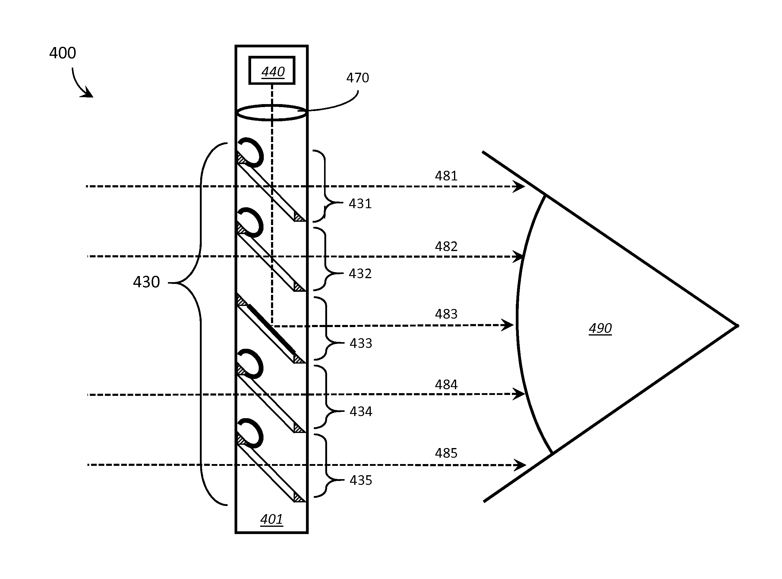
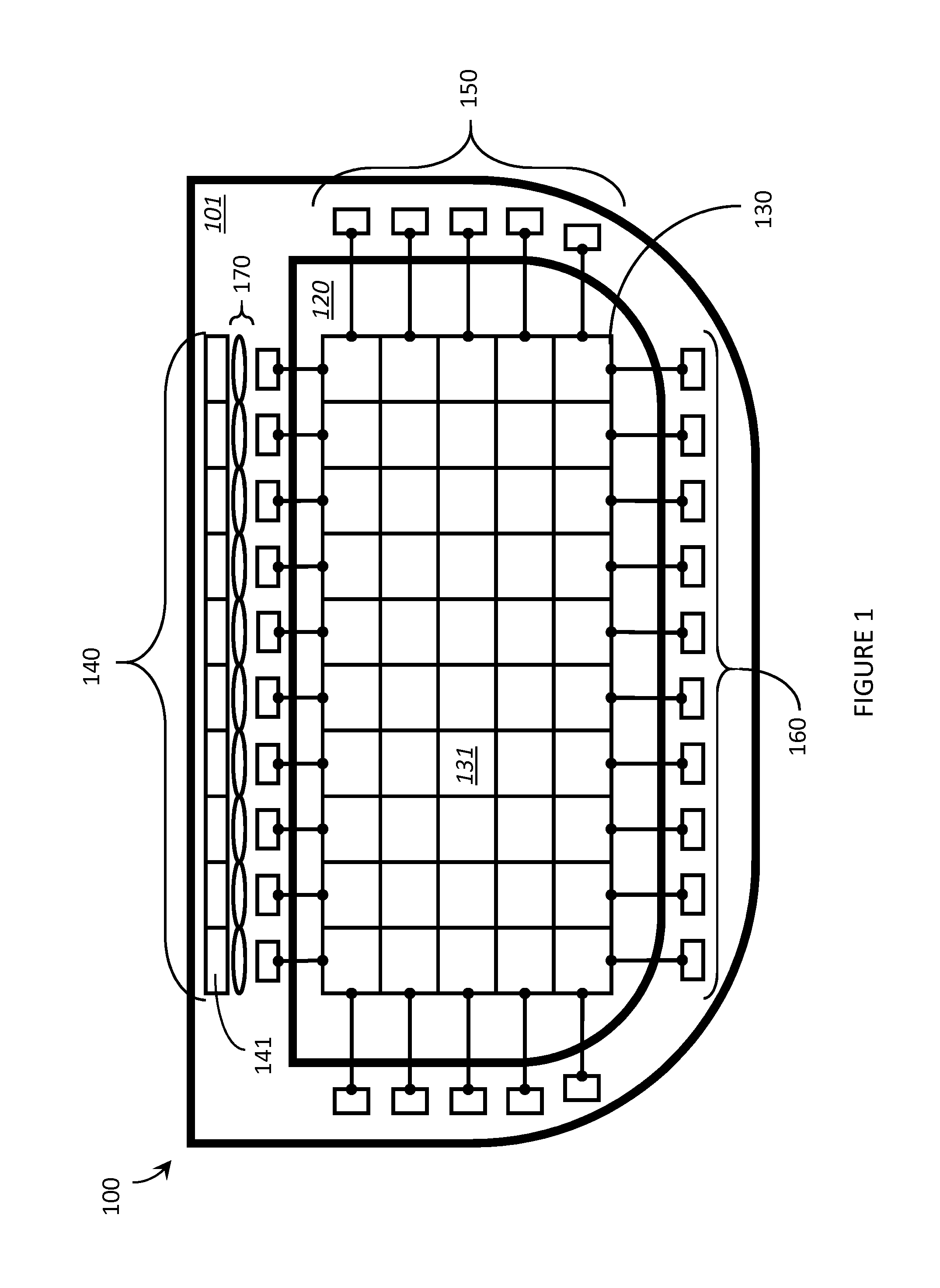
[0014]The first array of controllable reflectors may include X rows and Y columns, wherein X and Y are both integers greater than zero, and the first array of controllable reflectors may further comprise: a first set of X control signal lines, each control signal line in the first set of X control signal lines communicatively coupled to all of the controllable reflectors

Problems solved by technology

However, the convenience of being able to carry a portable electronic device has also introduced the inconvenience of having one's hand(s) encumbered by the device itself.
Thus, even though the wearable nature of a wearable electronic device allows the user to carry and, to at least some extent, operate the device without occupying their hands, accessing and/or interacting with content presented on an electronic display of a wearable electronic device may occupy the user's visual attention and limit their ability

Method used


Image

  • Systems, articles, and methods for wearable heads-up displays
  • Systems, articles, and methods for wearable heads-up displays
  • Systems, articles, and methods for wearable heads-up displays

Examples


Embodiment Construction

[0041]In the following description, certain specific details are set forth in order to provide a thorough understanding of various disclosed embodiments. However, one skilled in the relevant art will recognize that embodiments may be practiced without one or more of these specific details, or with other methods, components, materials, etc. In other instances, well-known structures associated with portable electronic devices and head-worn devices, have not been shown or described in detail to avoid unnecessarily obscuring descriptions of the embodiments.

[0042]Unless the context requires otherwise, throughout the specification and claims which follow, the word “comprise” and variations thereof, such as, “comprises” and “comprising” are to be construed in an open, inclusive sense, that is as “including, but not limited to.”

[0043]Unless the context requires otherwise, throughout the specification and claims which follow, the word “comprise” and variations thereof, such as, “comprises” a...


PUM


Abstract

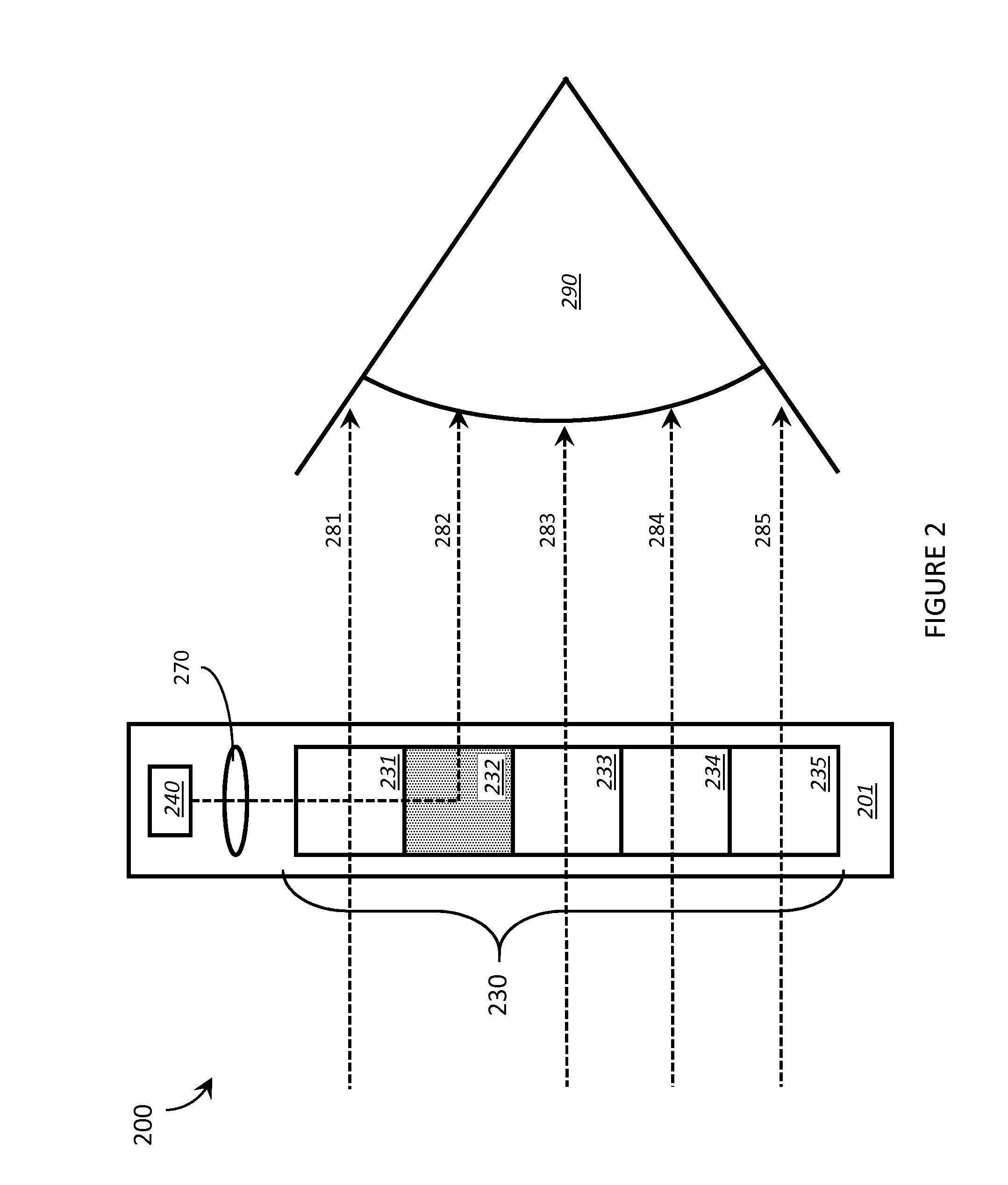
Systems, articles, and methods for transparent displays that are particularly well-suited for use in wearable heads-up display devices are described. Such transparent displays include a register of light sources that sequentially generates light signals representative of portions (e.g., pixels, and sometimes rows or columns of pixels) of an image. Light signals corresponding to the pixels are collimated and directed substantially in-plane with or co-planar to the transparent display and through, over, or across an array of controllable reflectors. Individual controllable reflectors in the array of controllable reflectors that correspond to the approximate pixel positions are activated to selectively reflect the light signals into the field of view of the user. Successive portions of the image are similarly generated and reflected in rapid succession until the entire image is displayed to the user. The controllable reflectors may include reflective microblinds, MEMS-based mirrors, and/or tunable polarization elements such as Kerr cells.

Description

BACKGROUND[0001]1. Technical Field[0002]The present systems, articles, and methods generally relate to electronic display technologies and particularly relate to electronic display technologies that are well-suited for use in wearable heads-up displays.[0003]2. Description of the Related ArtWearable Electronic Devices[0004]Electronic devices are commonplace throughout most of the world today. Advancements in integrated circuit technology have enabled the development of electronic devices that are sufficiently small and lightweight to be carried by the user. Such “portable” electronic devices may include on-board power supplies (such as batteries or other power storage systems) and may be designed to operate without any wire-connections to other, non-portable electronic systems; however, a small and lightweight electronic device may still be considered portable even if it includes a wire-connection to a non-portable electronic system. For example, a microphone may be considered a por...

Claims


Application Information

Patent Timeline
IPC IPC(8): G02B27/01G02B27/30G02F1/01G06F1/16G02B26/08
CPCG02B27/0172G06F1/163G02B27/0101G02B26/0816G02B2027/014G02F1/0136G02B27/30G02B2027/0178G02B2027/0132G02F1/0131G02F1/076G02B27/0905
Inventor BAILEY, MATTHEWMAHON, THOMAS
Owner GOOGLE LLC
Why Eureka
Try Eureka