
Interface and communication device

a communication device and interface technology, applied in the direction of antennas, antenna details, antenna couplings, etc., can solve the problems of difficult to address the deterioration, the mark, the position of the antenna, and the inability of the communication terminal to perform communication, so as to increase the degree of freedom when designing an antenna, high conductivity, and high sensitivity

Active Publication Date: 2015-07-23
MURATA MFG CO LTD
View PDF4 Cites 17 Cited by
  • Summary
  • Abstract
  • Description
  • Claims
  • Application Information

AI Technical Summary

Benefits of technology

The present invention allows for efficient communication with a device located on the same side as a display screen of a display device while maintaining a sufficient degree of freedom in designing an antenna. A spacer is used to eliminate a difference in level between the antenna coil and a magnetic member. The antenna coil is placed on the opposite side of the display screen, which increases the degree of freedom in designing the antenna and allows for the use of a high-conductivity material. As a result, the antenna has high sensitivity and can be manufactured at low cost. Overall, the invention allows for efficient communication with a device located on the same side as a display screen while maintaining design flexibility and sensitivity.

Problems solved by technology

However, in the case where a cover or the like that is made of a silicone rubber is mounted on the communication terminal, the mark, which indicates the position of the antenna, cannot be visually recognized from the outside.
In addition, in the case where a housing of the communication terminal is made from a metal such as aluminum or stainless steel, there are disadvantages in that an area in which the communication terminal can perform communication may sometimes be small and there is a possibility that the communication terminal cannot perform communication.
Consequently, in the case where a design change is made in a housing in which the display is to be accommodated after the display has been manufactured, and where the antenna characteristics deteriorate, it becomes difficult to address the deterioration.
Thus, it is difficult to obtain a sufficient Q value by using an antenna that includes a coil made of ITO, and there is a problem in that communication quality becomes inconsistent.

Method used


Image

  • Interface and communication device
  • Interface and communication device
  • Interface and communication device

Examples


first preferred embodiment

[0057]Various preferred embodiments of the present invention will be described below with reference to the drawings. In the description, an XYZ coordinate system that is defined by an X axis, a Y axis, and a Z axis, which are perpendicular to one another, is used for convenience of description.

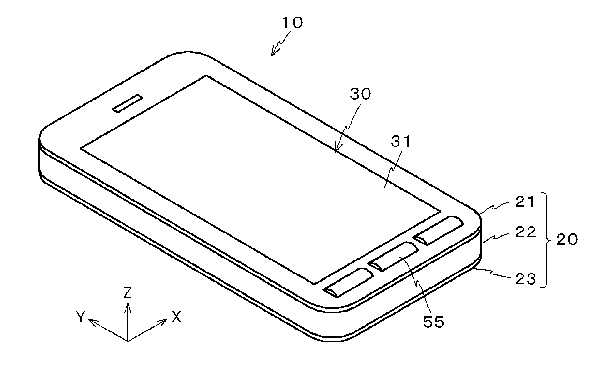
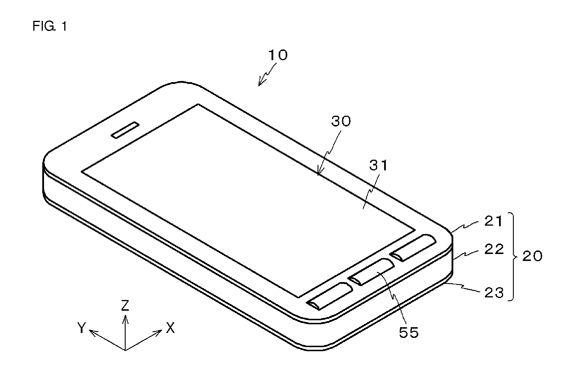
[0058]As illustrated in FIG. 1, a communication terminal 10 according to the present preferred embodiment preferably is a smartphone that includes an interface 30 that is accommodated in a housing 20. The interface 30 preferably is a graphical user interface including a touch panel.

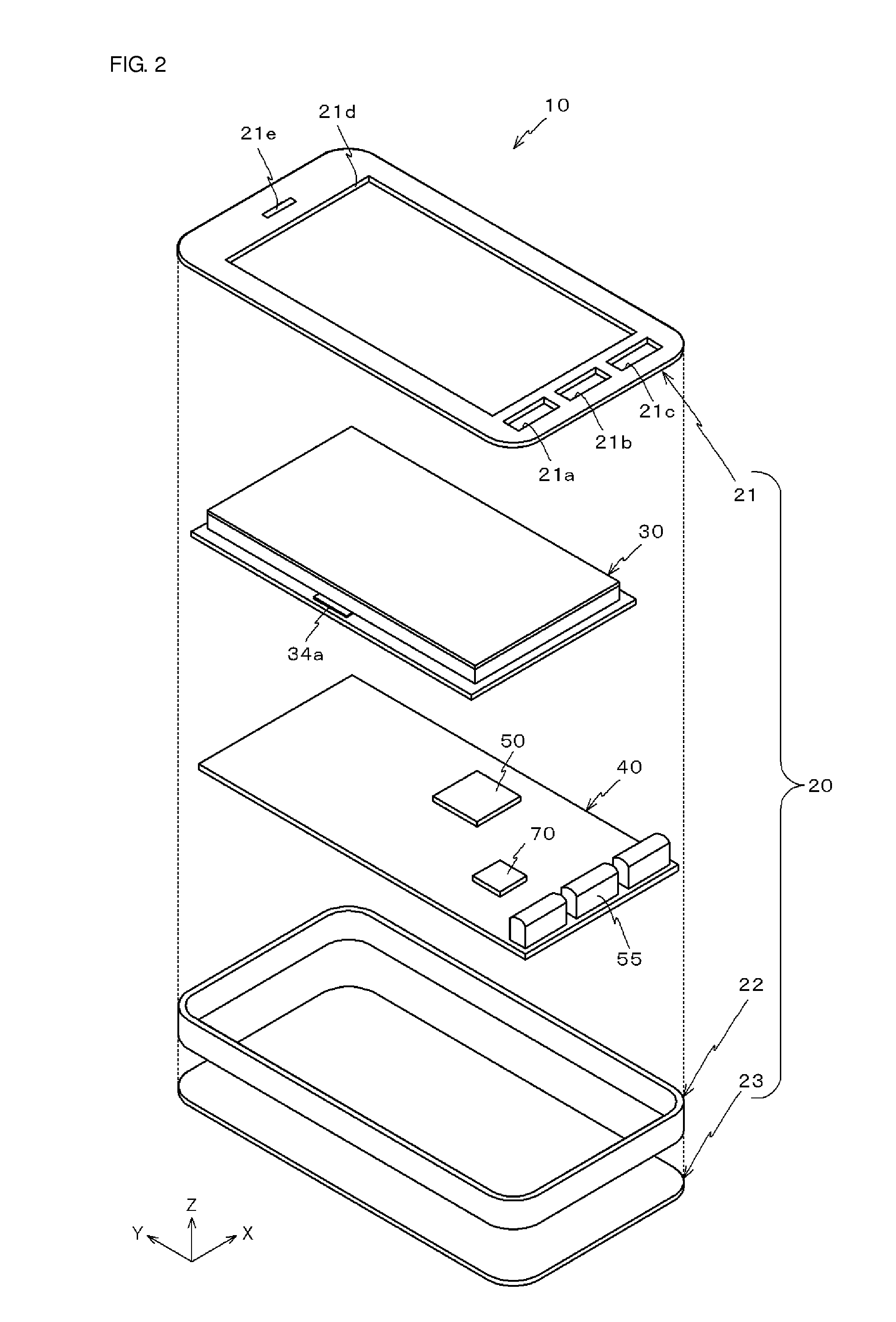
[0059]As illustrated in FIG. 2, the communication terminal 10 includes a front panel 21, a frame 22, and a rear panel 23 that define the housing 20, the interface 30 that is accommodated in the housing 20, and a control board 40.

[0060]The front panel 21 preferably is a rectangular or substantially rectangular panel whose longitudinal direction is parallel or substantially parallel to the Y-axis direction. A rectangu...

second preferred embodiment

[0099]A second preferred embodiment of the present invention will now be described with reference to the drawings. Note that components that are the same as or similar to those of the first preferred embodiment will be denoted by the same reference numerals, and descriptions thereof will be omitted.

[0100]A difference between the communication terminal 10 according to the present preferred embodiment and the communication terminal 10 according to the first preferred embodiment is that the interface 30 includes an antenna 34C as illustrated in FIG. 12. As illustrated in FIG. 12, the antenna 34C includes the protective member 61, the antenna coil 62, and the magnetic sheet 63 extending through the antenna coil 62.

[0101]As illustrated in FIG. 13, the protective member 61 is bent with the antenna coil 62 at two points and partitioned into three portions P1 to P3. The magnetic sheet 63 is received in a rectangular or substantially rectangular opening 64 that is located in the center porti...


PUM


Abstract

An antenna of a communication terminal is disposed on a side on which a bottom surface of a reflective plate, which is included in a display, is present. When the reflective plate is irradiated by an LED light source, the antenna cannot be seen from the side on which a display screen of the display is disposed. Accordingly, an antenna coil of the antenna does not need transparent electrodes and can be made of various materials each having a high conductivity. Therefore, the antenna has high sensitivity, low manufacturing cost, and very efficiently performs near field communication with an external device located on the display screen side of the display.

Description

BACKGROUND OF THE INVENTION[0001]1. Field of the Invention[0002]The present invention relates to an interface and a communication device.[0003]2. Description of the Related Art[0004]Communication terminals, representative examples of which are cellular phones, have recently had functions equivalent to those of personal computers as a result of advances in processors. In particular, a communication terminal that is provided with a graphical user interface (GUI) can provide a user with an interface for applications. Therefore, such a communication terminal is expected to be used in near field communication conforming to the near field communication (NFC) standard other than being used as a telephone.[0005]In the related art, in order to perform near field communication, an antenna that is disposed on a rear surface side of a communication terminal needs to be brought close to an external device with which the communication terminal communicates. Thus, a mark that indicates the positio...

Claims


Application Information

Patent Timeline
Patent Type & Authority Applications(United States)
IPC IPC(8): H01Q1/24H01Q7/00H01Q1/52
CPCH01Q1/241H01Q7/00H01Q1/526H01Q7/06H01Q1/22H01Q1/243
Inventor KATO, NOBORUOZAWA, MASAHIROTSUBAKI, NOBUHITO
Owner MURATA MFG CO LTD
Learn More