
Drill chuck

a drill chuck and chuck technology, applied in the field of new drill chucks, can solve the problems of affecting the operation of the drill chuck,

Active Publication Date: 2015-07-30
WEIHAI DAWANG MECHANICAL TECH LTD
View PDF11 Cites 3 Cited by
  • Summary
  • Abstract
  • Description
  • Claims
  • Application Information

AI Technical Summary

Benefits of technology

The present invention provides a new drill chuck that can protect cutters and can be easily opened. The design prevents damage to cutters and ensures an appropriate clamping force, avoiding the problem of difficulty or impossibility of opening the drill chuck. Cutters are also protected from pits due to excessive clamping force.

Problems solved by technology

The major problem with these types of drill chucks is: when these drill chucks are applied to electrical drills or other tools that rotate and knock in operation, such lasting knocking force will drive the clamping jaw to clamp the cutters continuously and cause an excessive clamping force, thus leaving pits on the cutters and damaging the cutters.
In addition, when the drill chuck stops or requires for replacement of cutters, due to the effect of the excessive clamping force generated by the clamping jaw to the cutters under the lasting knocking force, the drill chuck cannot be easily opened, making it much difficult to operate.

Method used


Image

  • Drill chuck
  • Drill chuck
  • Drill chuck

Examples


Embodiment Construction

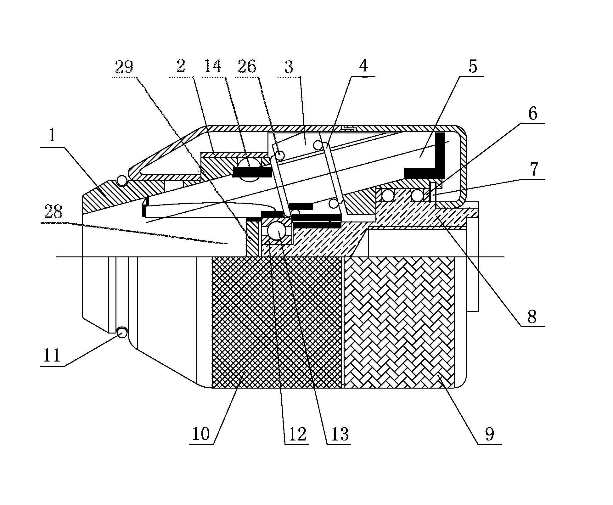
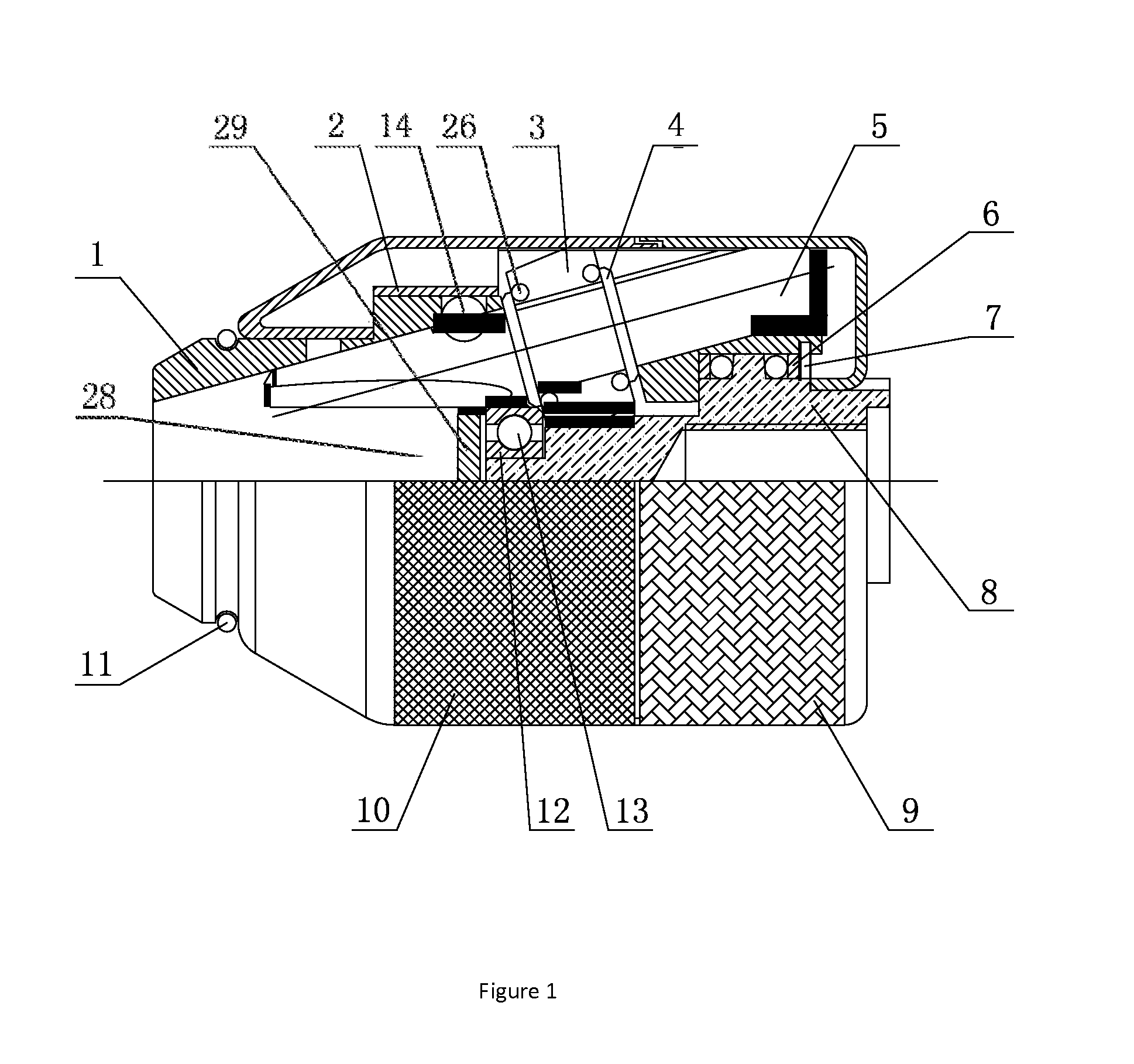
[0025]As FIG. 1 shows, the present invention mainly includes front-body 1, after-body 8, front sleeve 10, rear sleeve 9, clamping jaws 5, slave gears 3. After-body 8 is built in the front-body 1, and can only rotate transversely relative to the front-body 1. The front-body 1 has the clamping jaw hole 15. The clamping jaw 5 is located inside the clamping jaw hole 15. The slave gear 3 has the inner thread, which fits with the outer thread of clamping jaw 5. At the lower end of after-body 8 is master gear 19. The master gear 19 fits with slave gear 3. When after-body 8 rotates, slave gear 3 also rotates accordingly. Clamping jaw 5 is driven by gear 3 to move up and down.

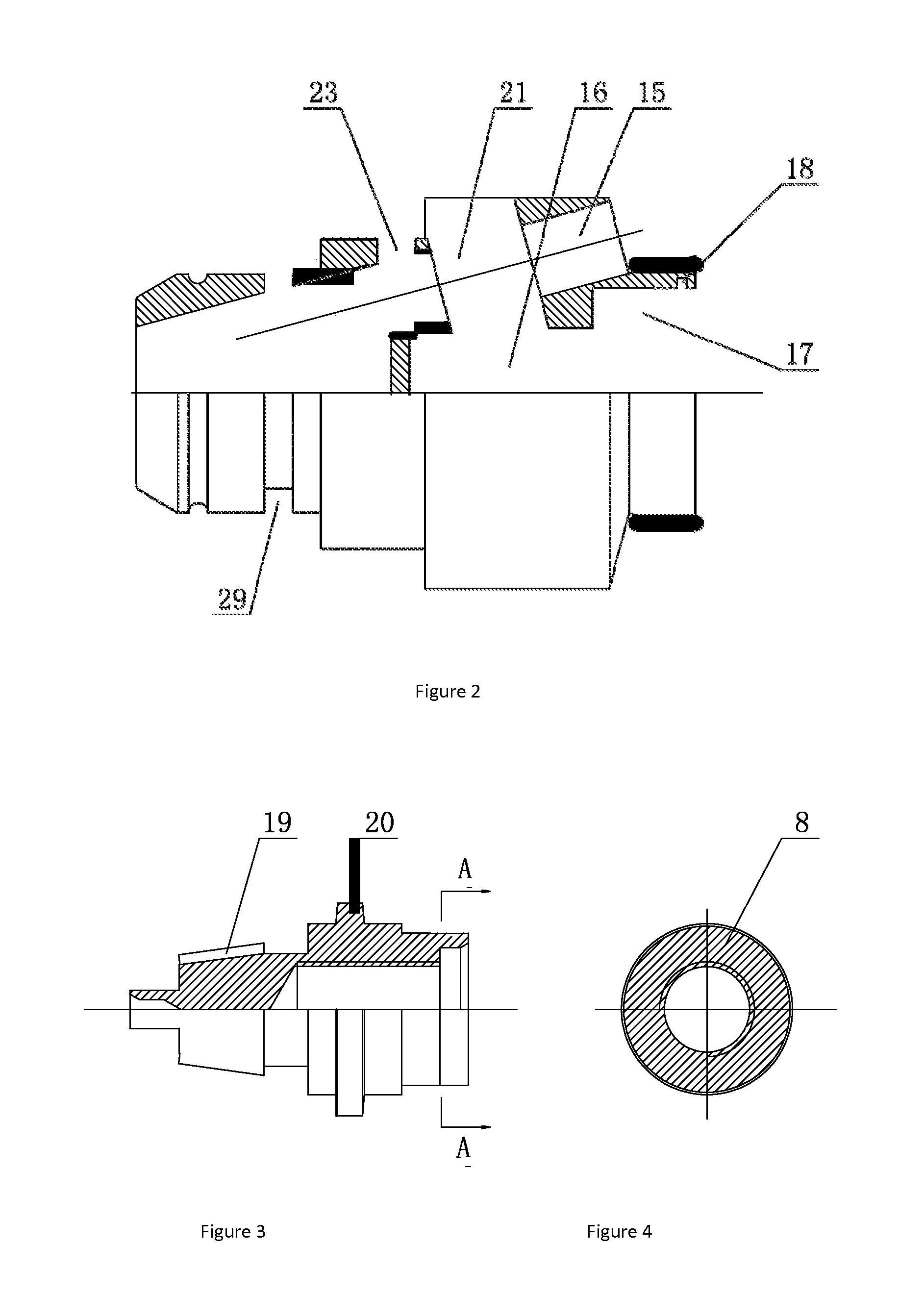
[0026]As FIGS. 2˜4 show, in the center position inside the rear end of front-body 1 are front groove 16 and rear groove 17. When after-body 8 is inserted into front-body 1, after-body 8 just fits with the two grooves. At the position on after-body 8 closest to the central part of front-body 1, i.e. the forefront of afte...


PUM


Abstract

The present invention provides a new drill chuck that resolves the problem that the excessive clamping force of the existing drill chuck makes it inconvenient to open the drill chuck and easily damages the cutters. The new drill chuck comprises a front-body, an after-body, and clamping jaws, wherein a thread is provided on the clamping jaw, the after-body is provided with master gears, slave gears are provided between the clamping jaws and the after-body, the master gear fits with the slave gear, a thread is provided inside the slave gear, and the thread of the slave gear fits with the thread of the clamping jaw.

Description

TECHNICAL FIELD[0001]The present invention relates to a fixture of cutters for mechanical processing, and particularly to a new drill chuck that is easy to open as well as protects cutters.BACKGROUND ART[0002]In production and processing activities, machine tools, electrical drills and other tools are often used for boring, milling and other operations. The drill chucks mounted on the working shafts of main engines of such equipment for holding bits, milling cutters and other cutters have been applied and improved for long, but are still observed with various deficiencies. By the source of the force in the drill chuck for pushing the clamping jaw to move up and down inside the clamping jaw hole, drill chucks are mainly classified into the following three types:[0003]The first one is the drill chuck that provides, from outside of the clamping jaw, the force for the clamping jaw to move up and down. Such drill chuck generally has the partial thread outside the clamping jaw. Such threa...

Claims


Application Information

Patent Timeline
Patent Type & Authority Applications(United States)
IPC IPC(8): B23B31/16
CPCB23B2231/24B23B31/16083B23B31/1207B23B31/1215B23B2260/07B23B2260/106Y10T279/17666
Inventor LIU, YAOTINGYU, ZUOZI
Owner WEIHAI DAWANG MECHANICAL TECH LTD
Learn More