

Zoom Lens, Imaging Optical Device, And Digital Equipment
a technology of imaging optical devices and zoom lenses, applied in the field of zoom lens systems, can solve problems such as large chromatic coma, and achieve the effects of reducing chromatic aberration, reducing chromatic coma, and correcting field curvatur
- Summary
- Abstract
- Description
- Claims
- Application Information
AI Technical Summary
Benefits of technology
Problems solved by technology
Method used
Image


Examples
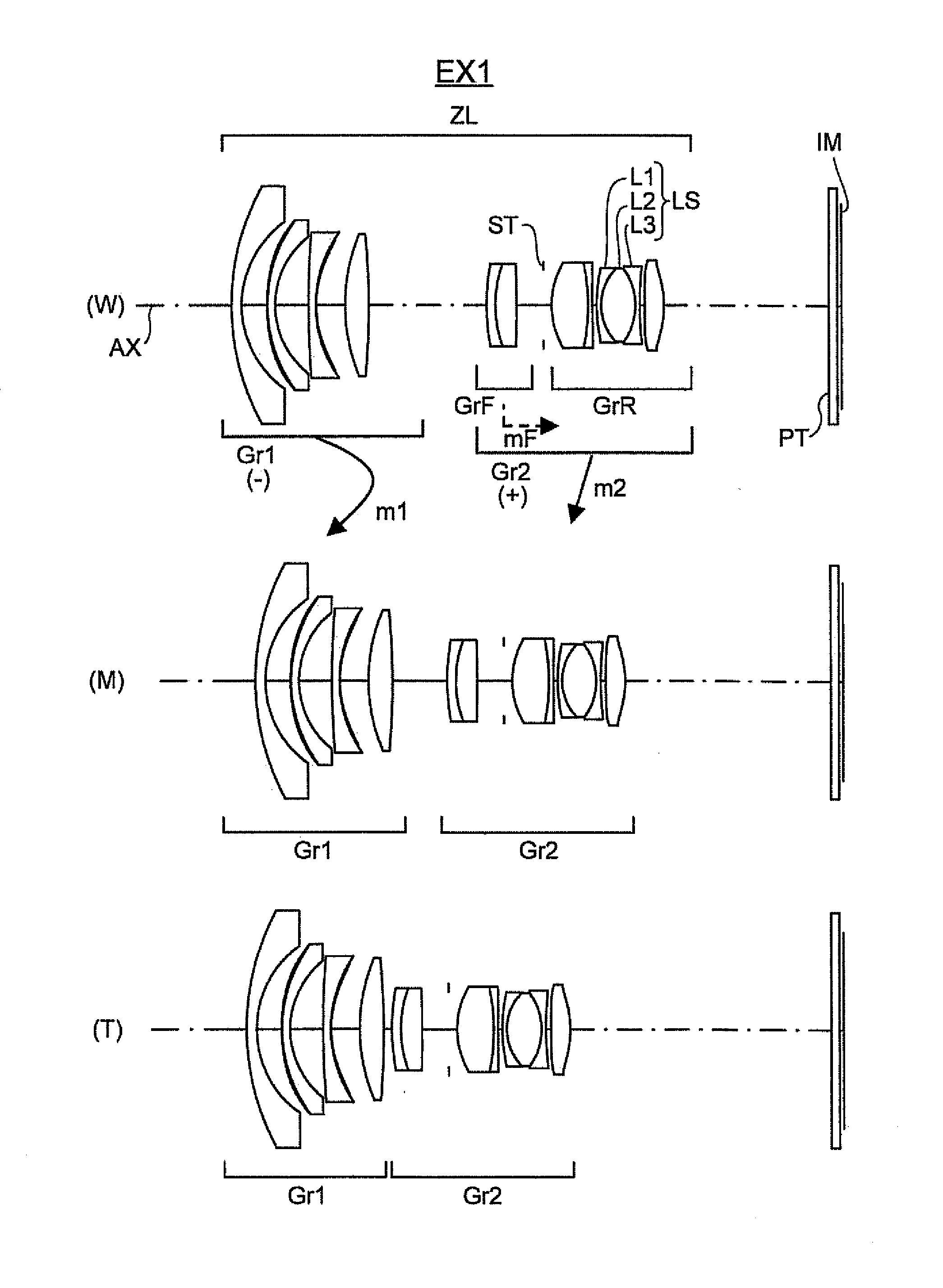
example 1
[0121]
Unit: mmSurface DataSurface No.rdndvdObject Surface∞d0 155.4662.301.7291654.67 222.8825.75 *342.4770.081.5140053.00 431.6161.801.7291654.67 519.4077.62 6201.3731.731.8042046.50 727.8730.081.5140053.00 *823.0596.63 939.9705.451.6889331.16 10−175.40126.97(Variable) 1149.3932.001.8051825.46 1225.9040.011.5140042.80 1325.9044.841.6476933.84 14−302.7846.15 15 (Aperture)∞1.90 1618.7918.371.4970081.61 17−46.1080.011.5140042.80 18−46.1081.001.7291654.67 191198.1931.00 2038.0881.001.8042046.50 2111.6170.011.5140042.80 2211.6177.851.4970081.61 23−13.9150.011.5140042.80 24−13.9151.001.7291654.67 2563.3111.21*26999.9954.411.5831359.39*27−21.94337.70(Variable) 28∞1.901.5168064.20 29∞1.00Image Surface∞0.00Aspherical Surface DataSurfaceKA4A6A8A10A12A1431.4871.168E−05−4.148E091.101E−121.894E−14−2.952E−17−9.759E−218−4.7153.700E−05−1.310E−072.082E−10−3.243E−131.792E−17−9.759E−21260.0002.136E−051.939E−071.663E−091.020E−1127−10.003−9.654E−051.095E−06−7.277E−095.471E−11Miscellaneous DataZoom Ratio...
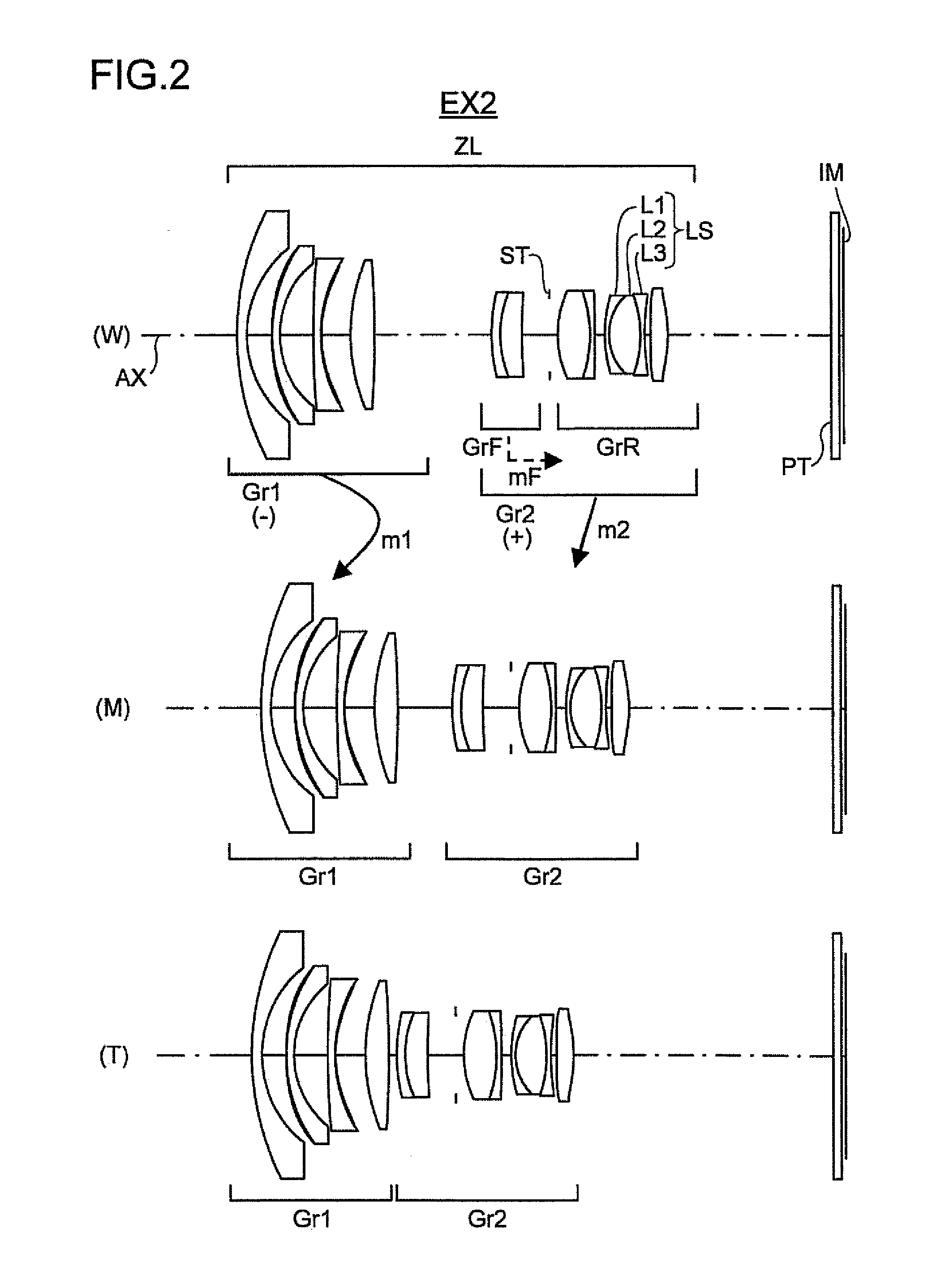
example 2
[0122]
Unit: mmSurface DataSurface No.rdndvdObject Surface∞d0 156.8942.301.7291654.67 223.1755.62 *344.1290.081.5140053.00 431.9091.801.7291654.67 519.2707.64 6189.9601.701.8042046.50 728.6920.081.5140053.00 *823.8926.86 940.1965.431.6889331.16 10−202.83726.95(Variable) 1136.0492.001.8051825.46 1221.7900.011.5140042.80 1321.7905.061.6476933.84 14148.3196.42 15 (Aperture)∞1.90 1621.2007.431.4970081.61 17−27.4610.011.5140042.80 18−27.4611.121.7291654.67 19−246.8572.33 2027.5381.001.8042046.50 2111.3170.011.5140042.80 2211.3177.151.4970081.61 23−23.8780.011.5140042.80 24−23.8781.001.7291654.67 2551.4421.34*261000.2133.951.5831359.39*27−28.05237.70(Variable) 28∞1.901.5168064.20 29∞1.00Image Surface∞0.00Aspherical Surface DataSurfaceKA4A6A8A10A12A1430.7321.552E−05−7.975E−091.063E−117.872E−15−2.952E−17−9.759E−218−3.9022.960E−05−1.061E−071.524E−10−2.983E−131.792E−17−9.759E−21260.0002.037E−053.707E−07−1.487E−092.256E−1127−14.275−5.950E−058.978E−07−5.962E−093.899E−11Miscellaneous DataZoom Rat...
example 3
[0123]
Unit: mmSurface DataSurface No.rdndvdObject Surface∞d0 156.7002.291.7291654.67 222.5545.87 *341.6540.081.5140053.00 431.0791.801.7291654.67 520.0607.48 6185.1982.801.8042046.50 727.9470.081.5140053.00 *823.1027.04 940.5305.291.6889331.16 10−214.87226.65(Variable) 1136.8511.031.8051825.46 1224.2270.011.5140042.80 1324.2274.831.6476933.84 14252.8026.02 15 (Aperture)∞1.90 1621.4337.211.4970081.61 17−28.1200.011.5140042.80 18−28.1201.401.7291654.67 19−363.9271.00 2030.9601.551.8348142.71 2112.0480.011.5140042.80 2212.0487.171.4970081.61 23−19.1650.011.5140042.80 24−19.1652.001.6729355.04 2546.3951.41*261001.9594.061.5831359.39*27−26.00537.70(Variable) 28∞1.901.5168064.20 29∞1.00Image Surface∞0.00Aspherical Surface DataSurfaceKA4A6A8A10A12A1432.5759.770E−06−7.840E−099.280E−12−4.014E−14−2.952E−17−9.759E−218−5.5774.396E−05−1.562E−072.102E−10−2.057E−131.792E−17−9.759E−21260.0001.808E−053.577E−07−8.150E−102.178E−1127−13.787−7.676E−051.055E−06−7.110E−095.003E−11Miscellaneous DataZoom Ra...
PUM
 Abstract
Description
Claims
Application Information