System, method and computer-accessible medium for providing a panoramic cone beam computed tomography (CBCT)

a computed tomography and cone beam technology, applied in the field of medical imaging, can solve the problems of compromising the accuracy of target delineation, difficult to identify the treatment target and surrounding critical organs for image-guided setup, and many drawbacks in the current implementation of cb

Inactive Publication Date: 2015-07-30
THE TRUSTEES OF COLUMBIA UNIV IN THE CITY OF NEW YORK
View PDF9 Cites 165 Cited by
  • Summary
  • Abstract
  • Description
  • Claims
  • Application Information

AI Technical Summary

Benefits of technology

[0014]Exemplary “panoramic CBCT” according to certain exemplary embodiments of the present disclosure can image targets (e.g., portions of patients) at the treatment position with an imaging volume as large as practically needed. Using the exemplary “panoramic CBCT” techniques, the target can be scanned sequentially from multiple view angles. For each view angle, a half scan can be performed with the imaging panel positioned in any location along the beam path. The panoramic projection images of all views for the same gantry angle can then be stitched together with the direct image stitching method and full-fan, half-scan CBCT reconstruction can be performed using the stitched projection images. Accordingly, the exemplary embodiments of the panoramic CBCT technique, system, method and computer-accessible medium can be provided which can image tumors of any location for patients of any size at the treatment position with comparable or less imaging dose and time.

Problems solved by technology

However, there may be many drawbacks in the current implementation of CBCT.
One problem is the small imaging volume (e.g., due to small imager size) compromising the accuracy of target delineation.
This imaging volume of full-fan, half-scan CBCT acquisition may not be large enough to encompass the full patient anatomy for almost all treatment sites, making it difficult to identify the treatment target and surrounding critical organs for image-guided setup.
A “truncated” imaging volume can also lead to incorrect CT numbers and reconstruction artifacts because the attenuation outside the imaging volume can be back-projected into the imaging volume.
However, the CT numbers obtained from these methods are approximate and truncation artifacts / distortions exist in reconstructed images.
Although this imaging volume may still not be large enough to cover the whole patient anatomy for most thoracic, abdominal and pelvic cases, the associated problems (incorrect CT numbers and artifacts) can be not as severe as those for the full-fan, half-scan acquisition.
However, half-fan CBCT can require full-scan (360°) gantry rotation, which is not always possible.
Moving the patient back and forth between the treatment and imaging positions can be uncomfortable for the patients, can prolong the treatment time, and can introduce additional uncertainties (e.g., patient motions) that may need to be monitored.
Moreover, this additional shift might compromise the accuracy of image guidance because the effect of an error in measuring rotation is amplified as the point of interest (e.g., treatment iso-center) gets farther from the axis of rotation (imaging iso-center).
Data redundancy can cause artifacts for half-scan CT / CBCT reconstruction using FBP-type procedures as some line integrals can be back-projected twice while most are considered only once.
CBCT reconstructions using the FDK algorithm can also be prone to inherent shading artifacts (also referred to as cone-beam artifacts), particularly for half-scan acquisition because the cone beam projection images acquired in a circular trajectory might not completely cover the Fourier space and thus, might not provide complete data.
A potential source of reconstruction artifacts for panoramic CBCT is imperfect image stitching due to uncertainties in imaging position or output fluctuation.
This fluctuation may cause artifacts and incorrect CT numbers in the reconstructed images because the backprojection of the projection images for each view angle can be unevenly distributed and concentrated in certain regions within the imaging volume.

Method used


Image

  • System, method and computer-accessible medium for providing a panoramic cone beam computed tomography (CBCT)
  • System, method and computer-accessible medium for providing a panoramic cone beam computed tomography (CBCT)
  • System, method and computer-accessible medium for providing a panoramic cone beam computed tomography (CBCT)

Examples


Embodiment Construction

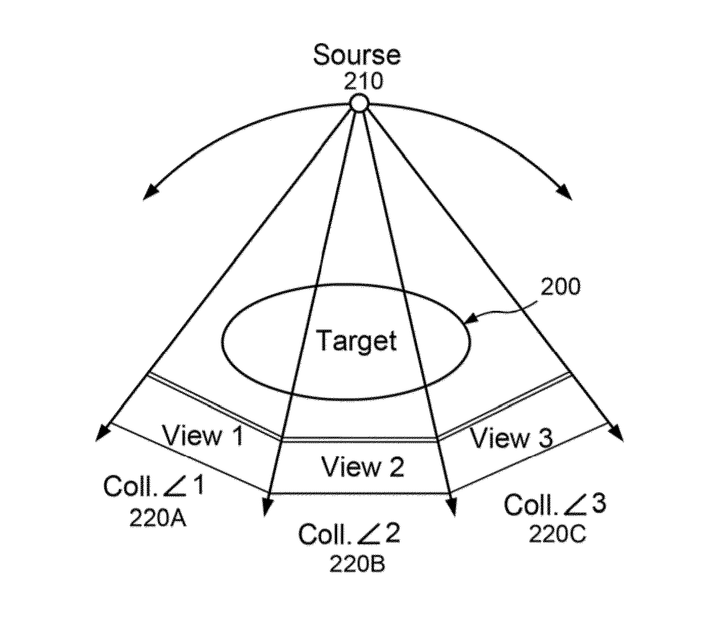
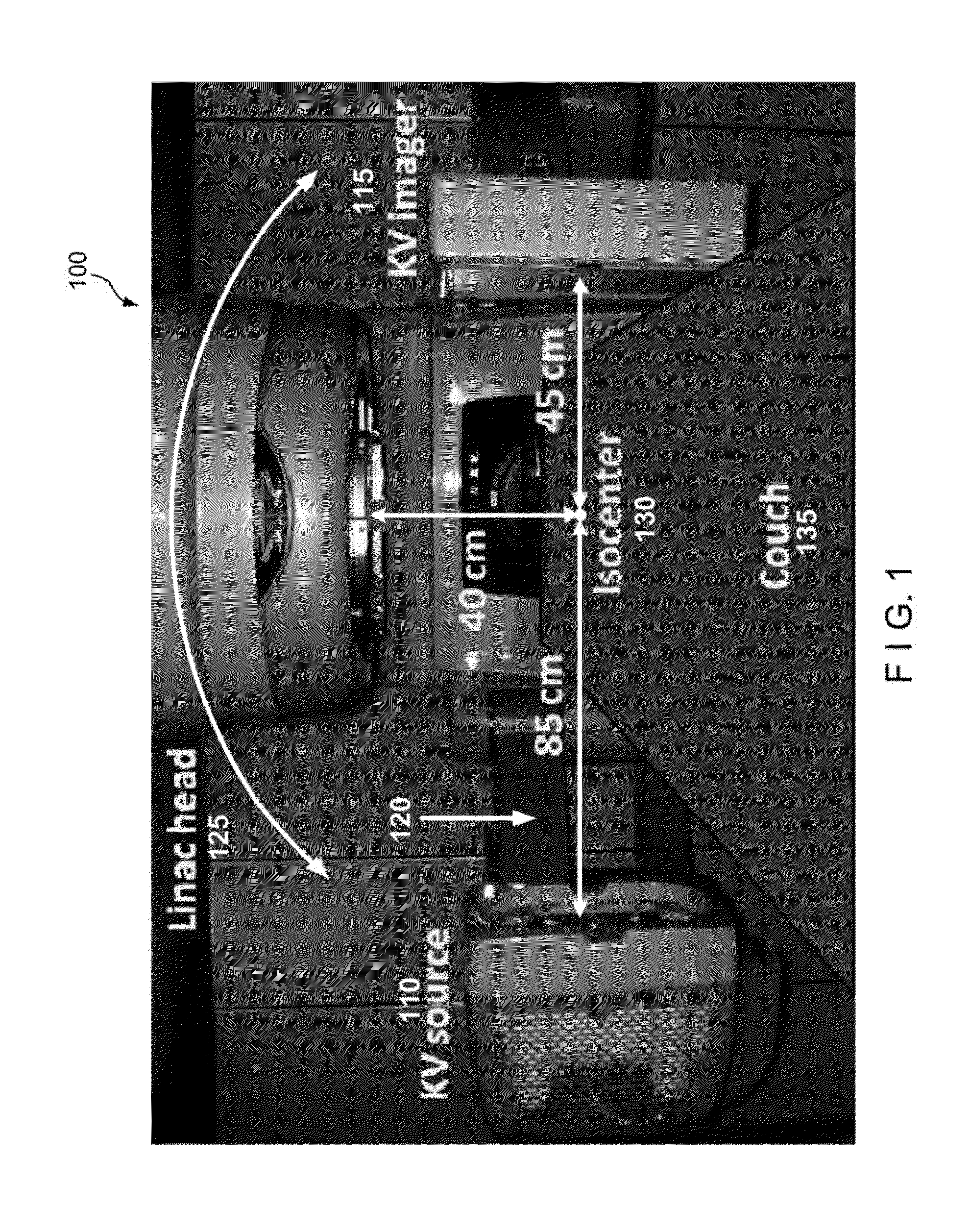
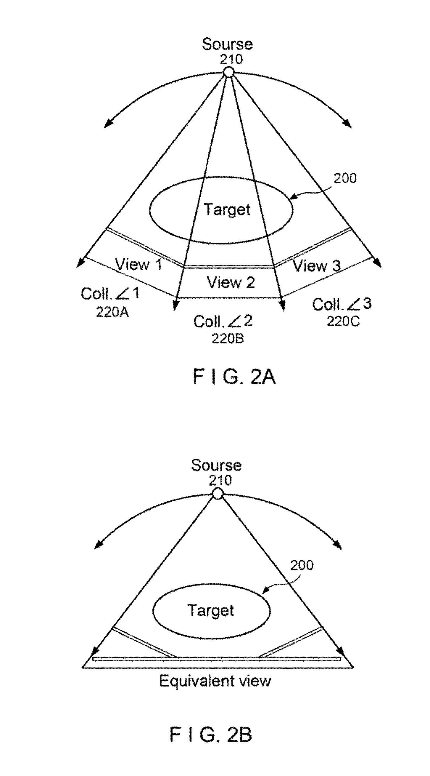
[0012]To address at least some of these drawbacks, exemplary embodiments of system, method and computer-accessible medium can be provided which can utilize and exemplary “panoramic CBCT” technique that can image patients at the treatment position with an imaging volume as large as practically needed. As shown in FIG. 1, a collision may not occur for a half-scan rotation (e.g., 180°+θcone) if the gantry head 125 rotates on the “far” side of the couch 135. According to certain exemplary embodiments of the present disclosure, it is possible to provide an imaging panel which can be large enough to encompass the whole anatomy for a full-fan, half-scan CBCT acquisition so that the linac head 125 does not have to rotate to the “near” side of the couch. Since an imaging panel of this size may not exist, according to one exemplary embodiment of the present disclosure, it is possible to split the view of the this large imaging panel into smaller ones that can be imaged with the existing imagi...


PUM


Abstract

Exemplary devices, procedures and computer-readable mediums for providing a projection image associated with at least one target. The projection image can be formed from a plurality of locations of a source arrangement. At each source location, a plurality of panoramic projection images associated with a target can be acquired. At least two of the panoramic projection images can be obtained at view angles which are different from one another. These panoramic projection images can be stitched together or otherwise combined. A resulting image can then be generated using a computed tomography procedure based on the stitched or combined projection images that are generated at the plurality of location.

Description

CROSS-REFERENCE TO RELATED APPLICATIONS[0001]This application relates to and claims priority from U.S. Patent Application Ser. Nos. 61 / 472,434, filed on Apr. 6, 2011, and 61 / 618,270, filed on Mar. 30, 2012, the entire disclosures of which are hereby incorporated herein by reference.FIELD OF THE DISCLOSURE[0002]The present disclosure generally relates to medical imaging, and in particular to exemplary embodiments of apparatus, methods, and computer-accessible medium for panoramic cone-beam computed tomography.BACKGROUND INFORMATION[0003]Image guided radiotherapy (IGRT) can include a radiotherapy procedure that uses imaging devices to guide treatment setup and dose delivery. Among many imaging / tracking devices used for IGRT, linear accelerator (linac) based cone-beam computed tomography (CBCT) is one of the most powerful tools for therapy guidance. CBCT has been used as a three-dimensional (3D) imaging method in IGRT to provide volumetric information for real-time patient setup, dose ...

Claims


Application Information

Patent Timeline
Patent Type & Authority Applications(United States)
IPC IPC(8): G06T11/60G06T11/00
CPCG06T11/60G06T2207/10081G06T11/008G01N23/046G01N2223/401A61B6/032A61B6/4085A61B6/4233A61B6/5205A61B6/5241A61N5/1049A61N2005/1061A61N5/1065G06T11/005G06T2211/432A61B6/582G01N2223/419G01N2223/612A61B6/583
Inventor CHANG, JENGHWACHAO, K.S. CLIFFORDZHOU, LILI
Owner THE TRUSTEES OF COLUMBIA UNIV IN THE CITY OF NEW YORK
Why Eureka
Try Eureka