Range Calibration of a Binocular Optical Augmented Reality System

a technology of augmented reality and binoculars, applied in the field of binocular optical seethrough augmented reality display calibration, can solve the problems of limited 3d capabilities, limited augmented reality support, and limitations of existing portable computing devices when it comes to enabling augmented reality applications

Active Publication Date: 2015-07-30
RICOH KK
View PDF4 Cites 43 Cited by
  • Summary
  • Abstract
  • Description
  • Claims
  • Application Information

AI Technical Summary

Benefits of technology

[0008]The specification describes range calibration procedures for a binocular optical see-through augmented reality display. One important advantage of the techniques described herein is the use of an area of

Problems solved by technology

Existing portable computing devices have fundamental limitations when it comes to enabling augmented reality applications.
While there exists a few near-eye disp

Method used


Image

  • Range Calibration of a Binocular Optical Augmented Reality System
  • Range Calibration of a Binocular Optical Augmented Reality System
  • Range Calibration of a Binocular Optical Augmented Reality System

Examples


second embodiment

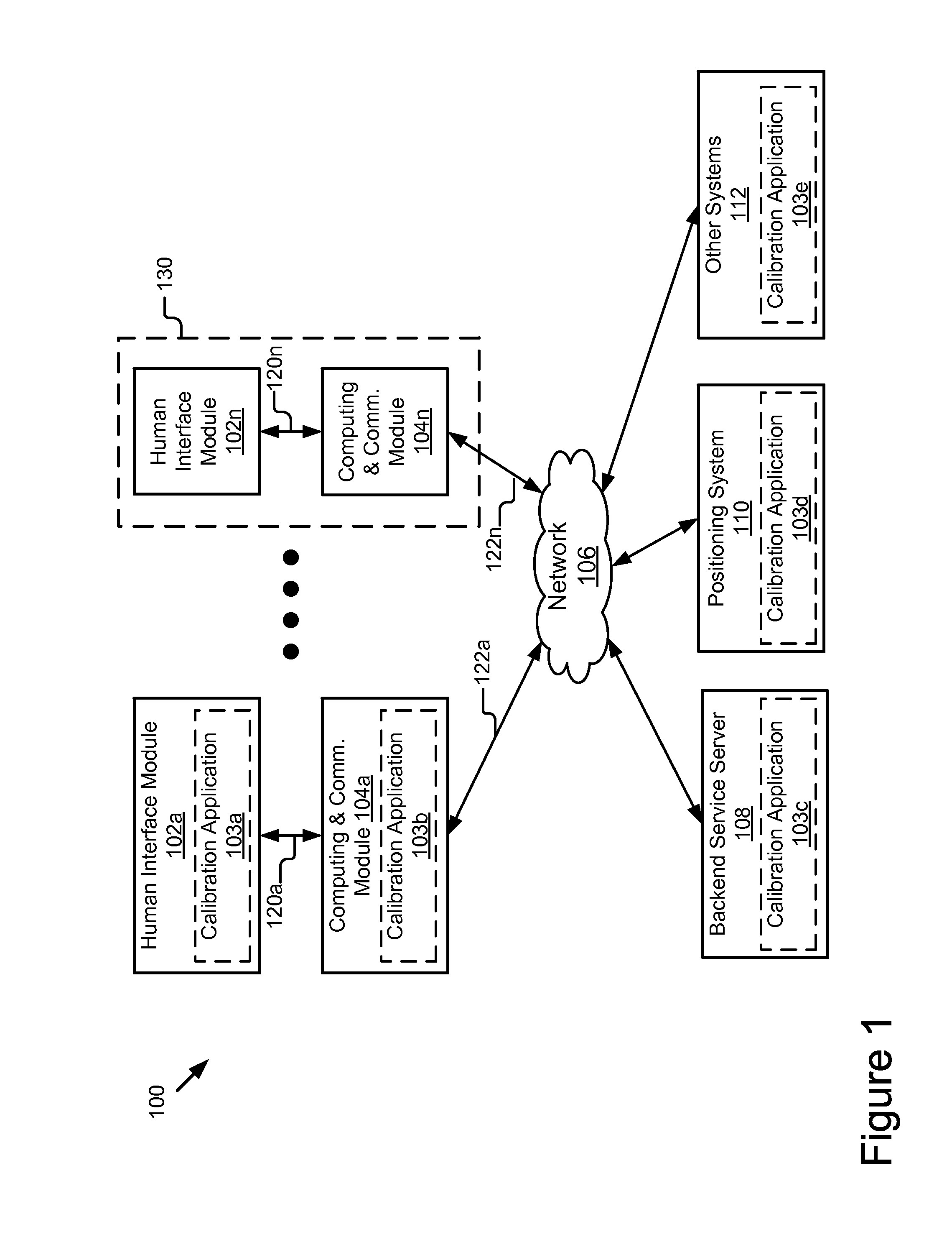
[0021]The human interface module 102 is in general a wearable device that permits a scene adapted overlay of virtual information on the real world objects. Regardless of the specific embodiment, reference to the terms “overlay,”“overlays” or “overlaid” refers to scene adapted overlay. In the embodiment of the present disclosure, the image delivery and display mechanism “overlays” information related to the user on a field of view or retrieved information is “overlaid” over a field of view. In other words, the user is able to see the real world that is not blocked by the overlay. In the preferred embodiment, the image delivery and display mechanism is a see-through medium through which the real world can be seen by the eyes of the user and on which virtual objects can be displayed overlaid on top of or next to real objects. For example, this overlay may be achieved with the image delivery and display mechanism projecting information into the eye so that the projected information can ...

first embodiment

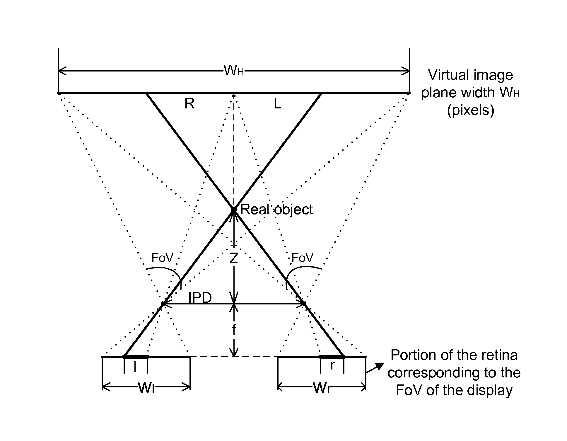
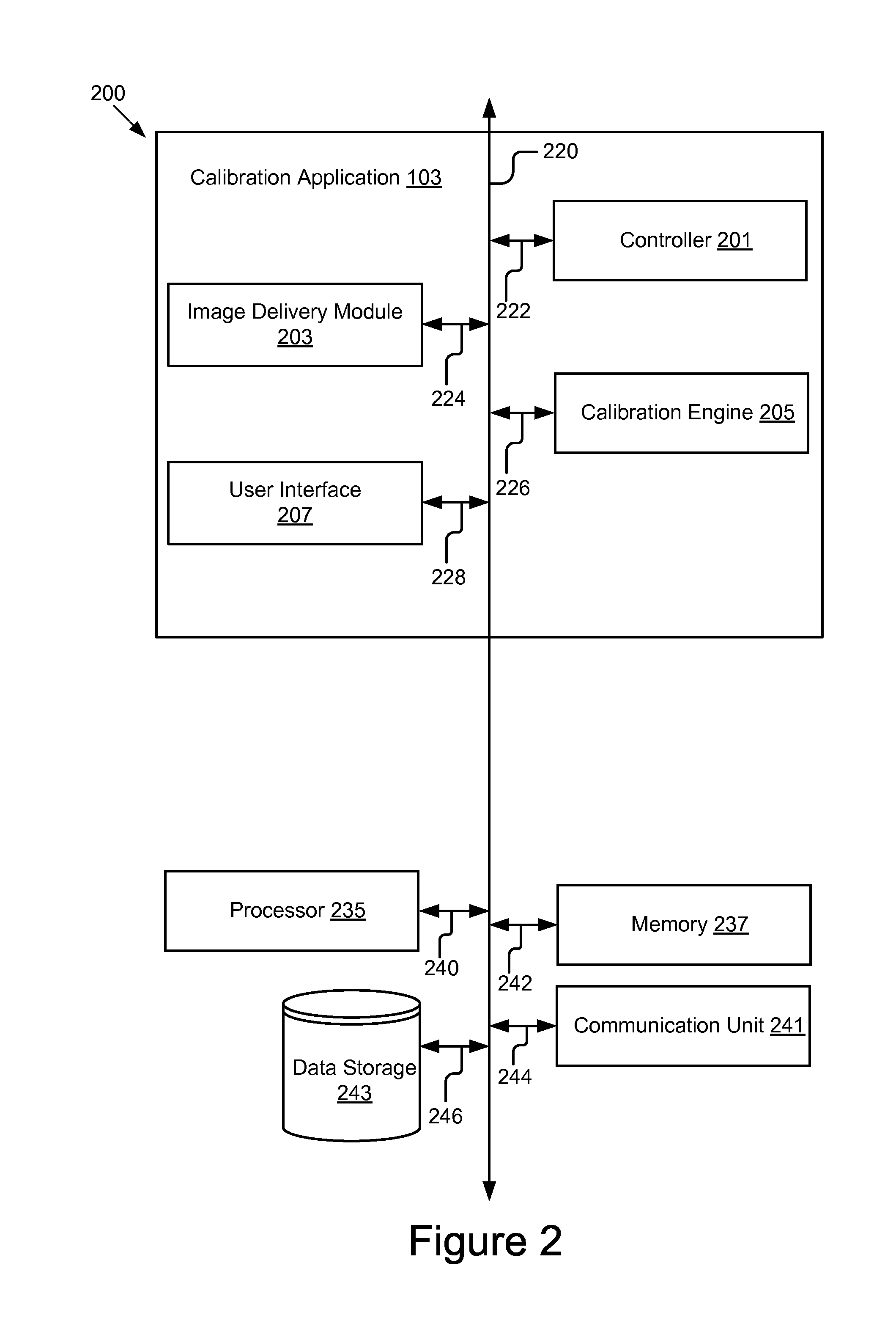
[0064]In the joint 3D calibration procedure, the calibration engine 205 first performs depth-disparity calibration by determining a depth disparity. The calibration engine 205 then uses the mapped disparity from the depth-disparity calibration to render the virtual target at the right depth. The calibration engine 205 then receives user input to move the virtual object on the display to align the 2D pixel position of the virtual object on the display with the real-world object. In one embodiment, the calibration engine 205 determines whether the calibration is complete (e.g., the user sees that the virtual object is aligned in depth and position with the real-world object). If the calibration is complete the disparity value is stored or recorded along with the depth. As noted above, the calibration can be determined as completed by the calibration application 103 or based on input from the user. If the calibration is determined incomplete, the calibration engine 205 continues to rec...


PUM


Abstract

The disclosure includes a system and method for calibrating a binocular optical see-through augmented reality display. A calibration application renders one or more images of a virtual object on the one or more displays of the human interface device, and receives a user input to adjust a position of the one or more images on the one or more displays. In response to the input, the calibration application identifies a first and second boundary of a target range surrounding a real-world object at a first and second depth, respectively. The calibration application determines a first and second disparity corresponding to the first and second boundary and may record the disparities in relation to the depth of the real-world object.

Description

CROSS REFERENCE TO RELATED APPLICATIONS[0001]The present application claims priority, under 35 U.S.C. §119, of U.S. Provisional Patent Application Ser. No. 61 / 933,178, filed Jan. 29, 2014 and entitled “Binocular Optical See-Through System and Associated Calibration Procedure,” which is incorporated herein by reference in its entirety.BACKGROUND[0002]1. Field of the Invention[0003]The specification relates to calibrating a binocular optical see-through augmented reality display based on user input. In particular, the specification relates to a system and method for calibrating a binocular optical see-through system using disparity ranges. Still more particularly, the specification relates to a system and method for calibrating using a fusional range or a tolerance range.[0004]2. Description of the Background Art[0005]Existing portable computing devices have fundamental limitations when it comes to enabling augmented reality applications. While there exists a few near-eye displays tha...

Claims


Application Information

Patent Timeline
IPC IPC(8): H04N13/04G06T7/00G06T19/00G02B27/01
CPCH04N13/0425G02B27/0172H04N2013/0465G06T19/006G06T7/002G02B27/017G02B2027/0127G02B2027/0138G02B2027/014H04N13/128H04N13/275G06T11/00G06T3/4038G06T19/00G06T15/20G09G5/14G06T7/593G06T19/20G06T7/85H04N2013/405
Inventor WU, WANMINTOSIC, IVANA
Owner RICOH KK
Why Eureka
Try Eureka