Dual bag filter with spacer

a filter cartridge and spacer technology, applied in the direction of filtering separation, moving filter element filter, separation process, etc., can solve the problem that the fluid with entrained contaminants bypasses the filter cartridg

Inactive Publication Date: 2015-08-06
PALL CORP
View PDF13 Cites 6 Cited by
  • Summary
  • Abstract
  • Description
  • Claims
  • Application Information

AI Technical Summary

Benefits of technology

[0003]The present disclosure describes a filter which is suitable for use in a filter housing. The filter described herein is formed from a felt material. The filter described herein is suitable for use in a variety of filters, such as bag filters, pleated filters, cartridge filters or other filters as are known. The felt material is formed from fibers of varying diameters. The felt material includes three layers which are woven together, a first layer, a second layer, and a third layer. There is a fourth material that constrains the felt material to a maximum size and it is smaller than the felt material. The first layer is formed from fibers having a relatively large diameter. The second layer is formed from fibers having a relatively small diameter. The third layer is formed from fibers having a relatively large diameter. With this configuration, fluid enters the filter through the first layer and exits the filter through the third layer. The first layer serves to filter out large particles and the second layer serves to filter out small particles. The first and third layers serve to provide structure and support to the filter to allow fluid passage and to prevent the second layer from folding over on itself. The fourth material prevents the felt material from expanding beyond the allowable size for use in a filter housing. The felt material is in the shape of a bag and includes an interior. A rigid core is carried in the interior of the felt material. The rigid core is generally tubular in shape. The rigid core is defined by a cylindrical wall which defines an opening at each end and an interior fluid pathway. Fluid entering the filter enters through one of the openings in the ends of the rigid core, and then passes out of the rigid core through one or more apertures formed through the cylindrical wall. The fluid exiting the apertures formed through the cylindrical wall is next filtered by the felt material before exiting the filter housing. The rigid core helps to prevent the felt material from collapsing on itself. The rigid core provides a fluid pathway along the height of the filter. The rigid core aids in inserting the filter in the filter housing.

Problems solved by technology

It is also necessary to maintain a fluid tight seal between the inlet chamber and the outlet from the filtering vessel, on that all of the fluid communicated into the inlet chamber must communicate through the filtering media; it is undesirable that any fluid with entrained contaminants bypasses the filter cartridge and passes directly to the outlet.

Method used


Image

  • Dual bag filter with spacer
  • Dual bag filter with spacer
  • Dual bag filter with spacer

Examples


Embodiment Construction

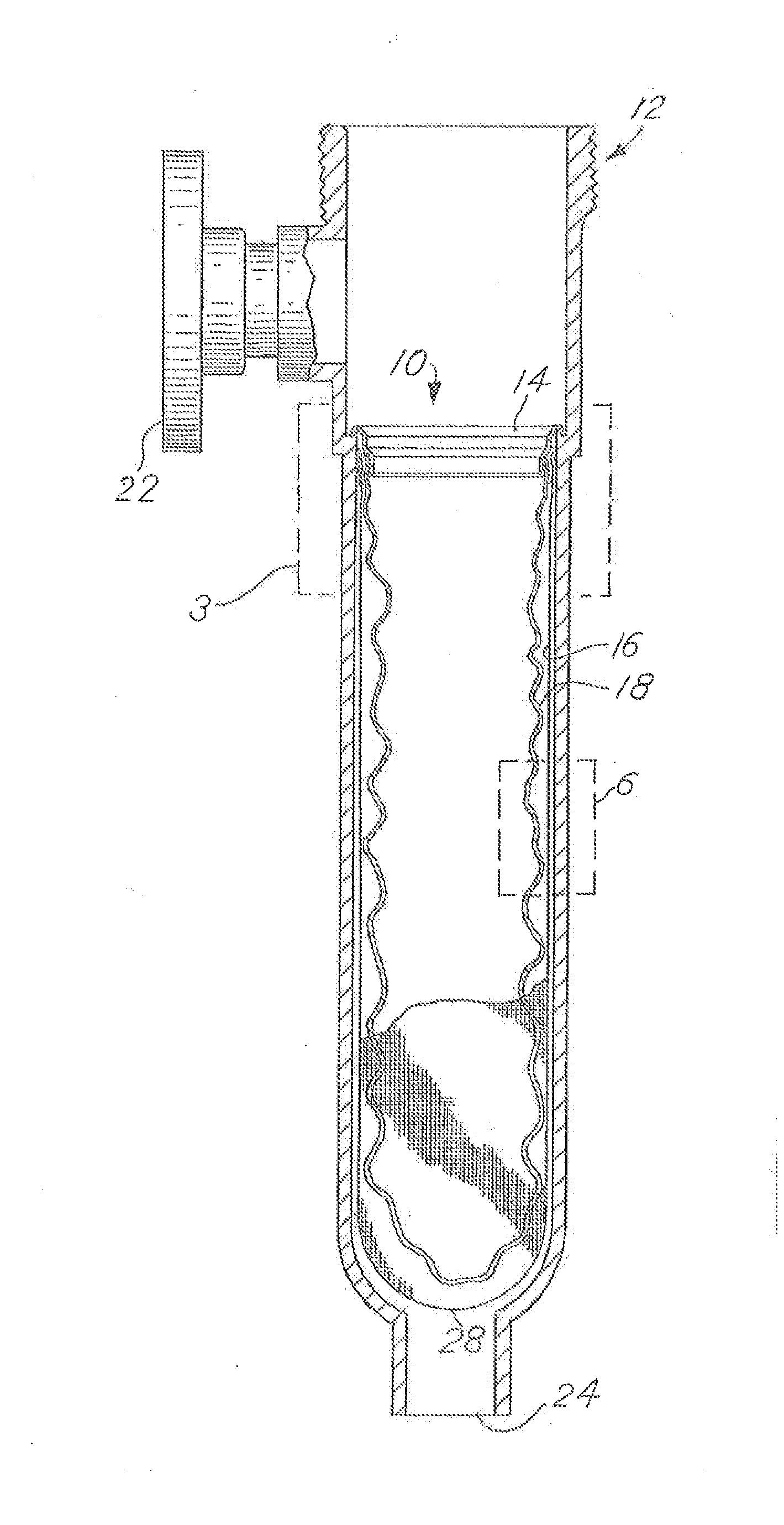
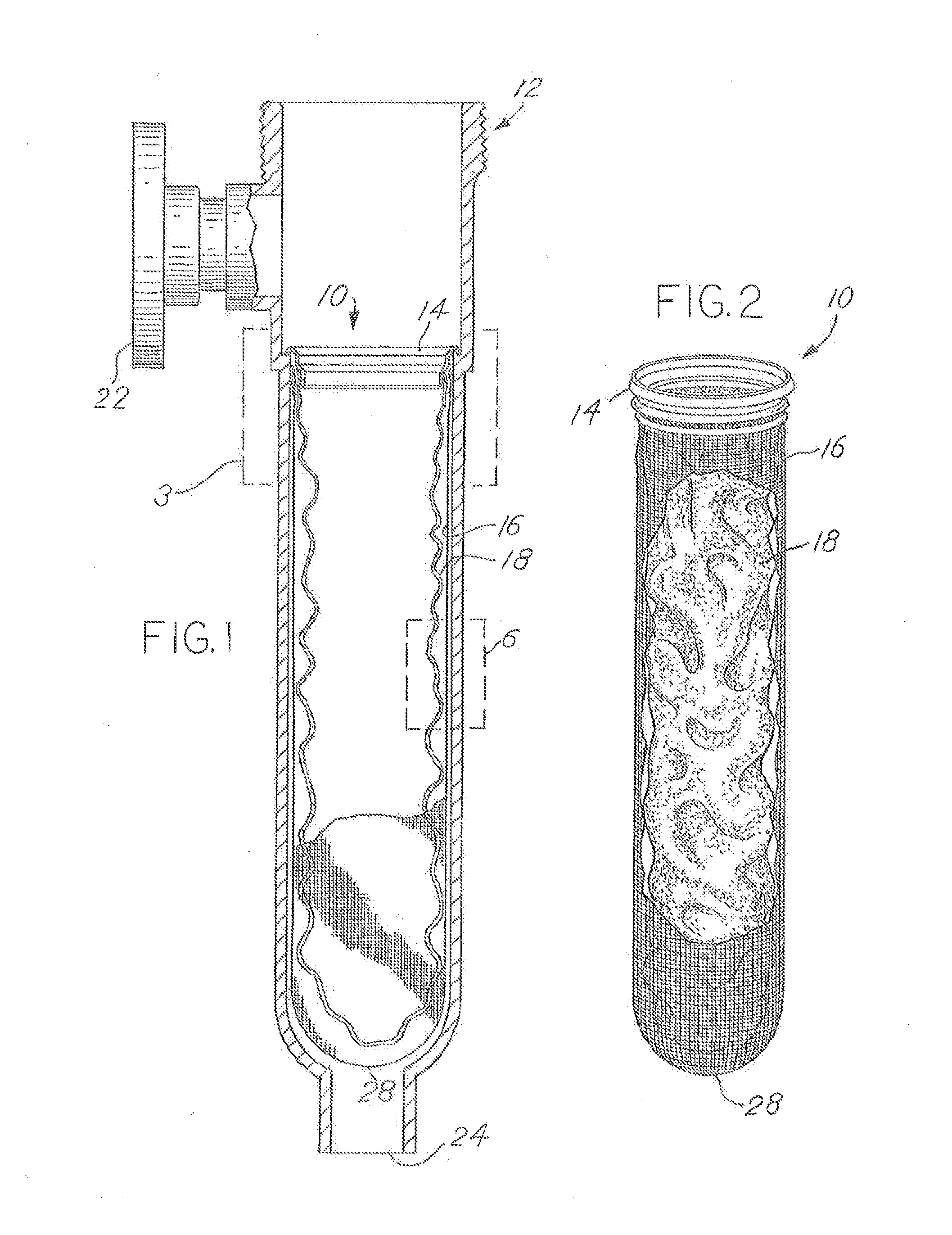
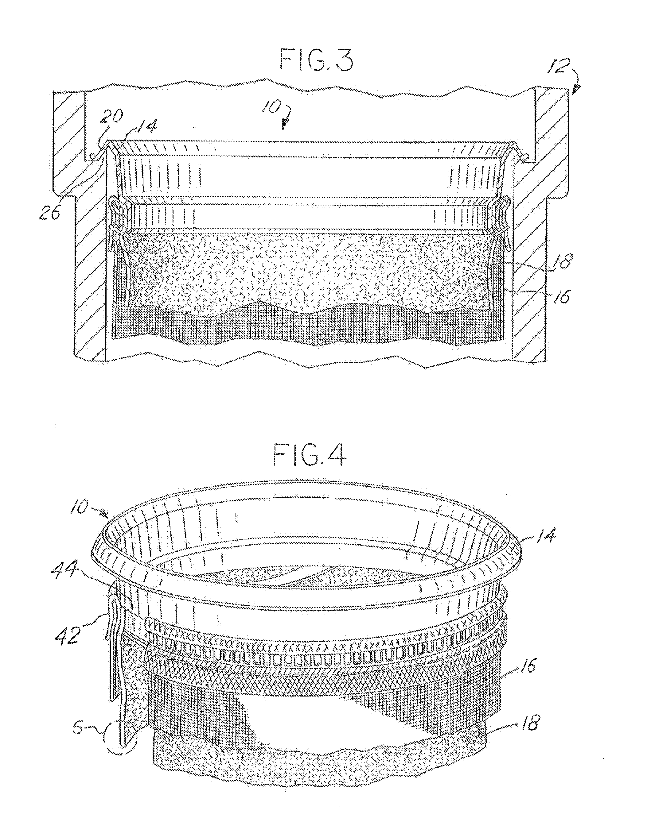
[0012]In reference to the several FIGS, elements which are common among the FIGS are referenced by the same ordinal. Any directional references herein, such as above, below, up, down, or similar terminology, are in reference to the spatial relationship of the elements as shown in a given FIG. It is appreciated that the elements described herein could be used in any number of spatial orientations, and as such any directional references herein are merely to aid in the description provided herein and do not limit use.

[0013]The present disclosure describes an improved filter element 10. The filter element 10 is suitable for being used in combination with a housing 12. In one instance, the filter element 10 is a bag-type filter, in other instances the filter element 10 is a cartridge filter or a pleated filter. The filter element 10 is suitable for filtering fluids. Generally speaking, the filter functions by filtering solids from a fluid.

[0014]Referring to FIGS. 1-4, the filter is forme...


PUM

PropertyMeasurementUnit
flexibleaaaaaaaaaa
surface areaaaaaaaaaaa
poreaaaaaaaaaa

Abstract

A dual bag filter is provided where a replaceable filter element resides in and is sealed to a filter housing. The filter element has a. mounting ring, an inner bag, and an outer bag. The inner bag is sized such that it has more surface area than the outer bag and is constrained by the outer bag. The inner bag is formed from a filter medium of different densities such that when the inner bag is crumpled, fluid flow is not restricted. A perforated central core keeps opposing sides of the inner bag from making contact.

Description

CROSS-REFERENCE TO RELATED APPLICATION[0001]This application claims the benefit of U.S. Provisional Application No. 61 / 842,258, filed Jul. 2, 2013 and 61 / 935,573, filed Feb. 4, 2014, the disclosures of which are hereby incorporated by reference.BACKGROUND OF THE INVENTION[0002]Large filtering vessels are commonly used for filtering industrial chemicals, such as solvents, cleaning fluids, etc, Such filtering devices are of two different types. One type uses a filtering bag that is suspended within a liner within the filtering vessel. The fluid to be filtered is communicated into the bag, and then communicates through the wall of the bag and the liner to the fluid outlet. Another type of filtering device uses a filtering cartridge mounted within the vessel. The filter cartridge defines an outer circumferential surface which cooperates with the wall of the filtering vessel to define an inlet chamber. The filter cartridge further includes a center core extending coaxially within the car...

Claims


Application Information

Patent Timeline
Patent Type & Authority Applications(United States)
IPC IPC(8): B01D29/27B01D29/58
CPCB01D29/58B01D29/27
Inventor MORGAN, III, HOWARD WILLIAM
Owner PALL CORP
Why Eureka
Try Eureka