Pipe float

Inactive Publication Date: 2015-08-06
SECURITY PAKS INT LLC D B A SPI PROD
View PDF11 Cites 0 Cited by
  • Summary
  • Abstract
  • Description
  • Claims
  • Application Information

AI Technical Summary

Benefits of technology

The invention is a pipe float made up of multiple sections that can be joined together to form a continuous passage for a pipe. Each section has inner surfaces that make engagement lines with the pipe when assembled, allowing for a range of pipe diameters to be accommodated. The sections can stack or nest with each other, making transportation and storage easier. The technical effect of this invention is to provide a flexible, customizable, and easily transported / stored pipe float that can be assembled quickly and easily.

Problems solved by technology

Members with curved surfaces, for example elongated substantially cylindrical surfaces, present challenges in terms of successfully engaging and holding the surfaces over extended periods of use.
By this improved configuration, it is intended to inhibit longitudinal movement of the pipe float along the pipe, which might cause the pipe floats to lose their longitudinal spacing with the result that a portion of the pipe sinks.
It is also intended to inhibit rotational movement of the pipe float about the pipe, which may result in wear on the pipe and / or a decrease in engagement between the pipe and the pipe float.

Method used


Image

  • Pipe float
  • Pipe float
  • Pipe float

Examples


Embodiment Construction

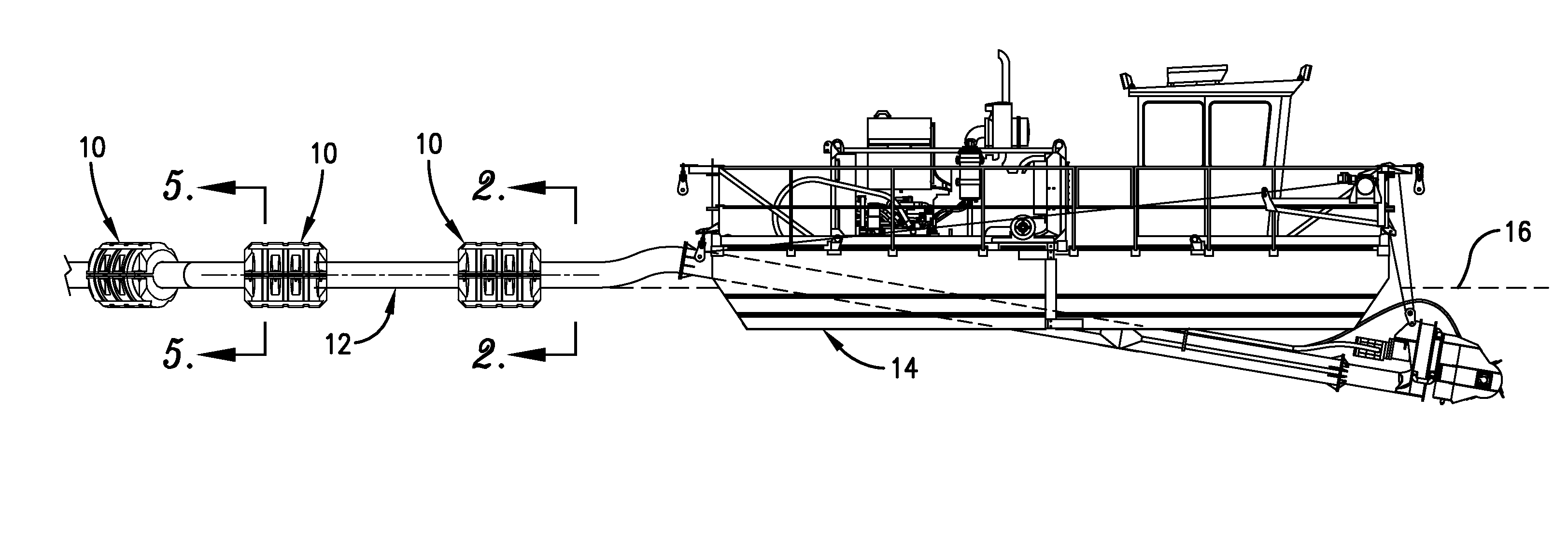
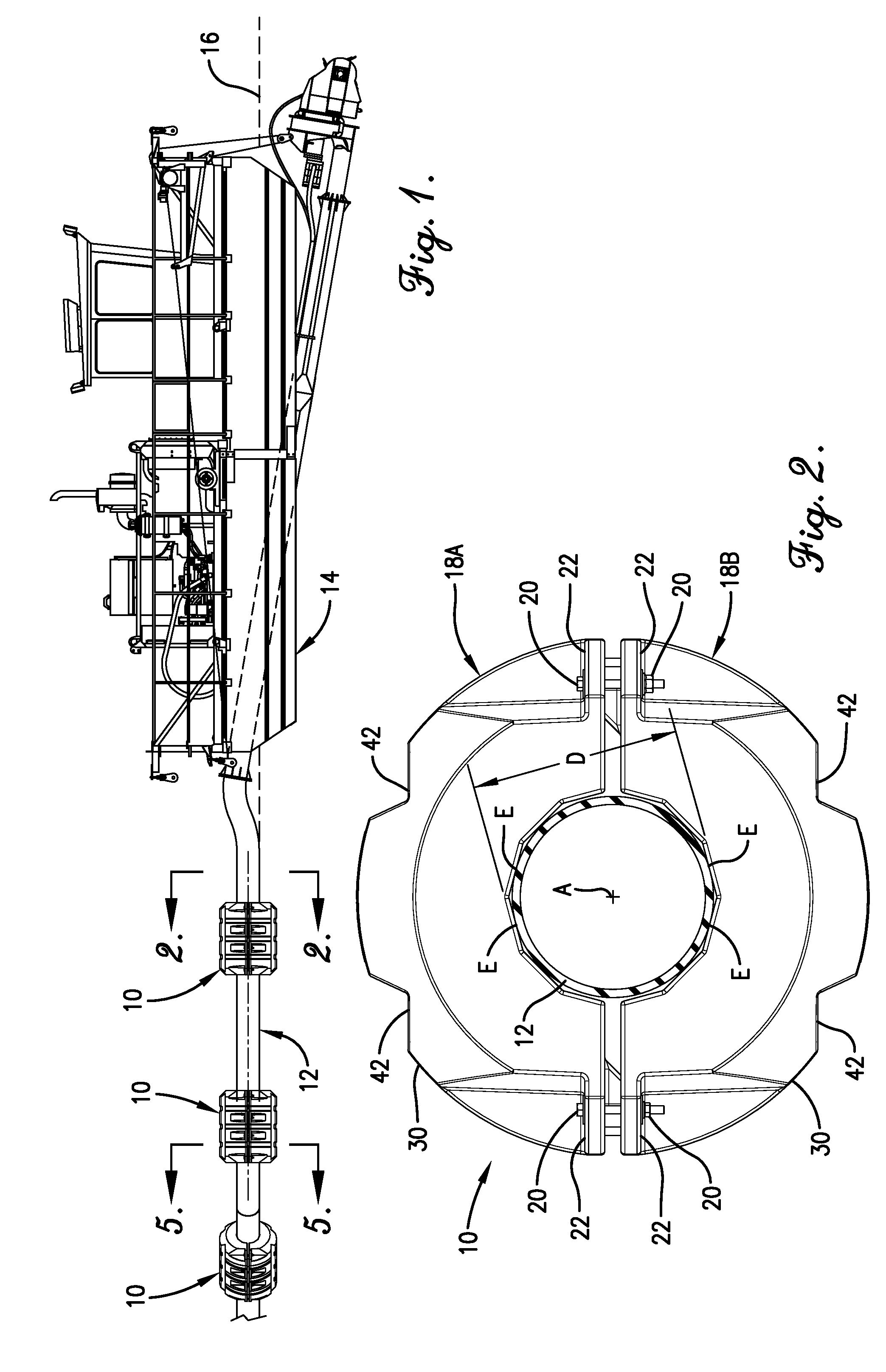
[0016]Referring now to the drawings, FIG. 1 shows a plurality of pipe floats 10 in spaced relationship coupled to a pipe 12 which is connected to a dredge 14 floating on the surface 16 of a body of water. This is only one use the pipe floats 10 and is provided for purposes of illustration.

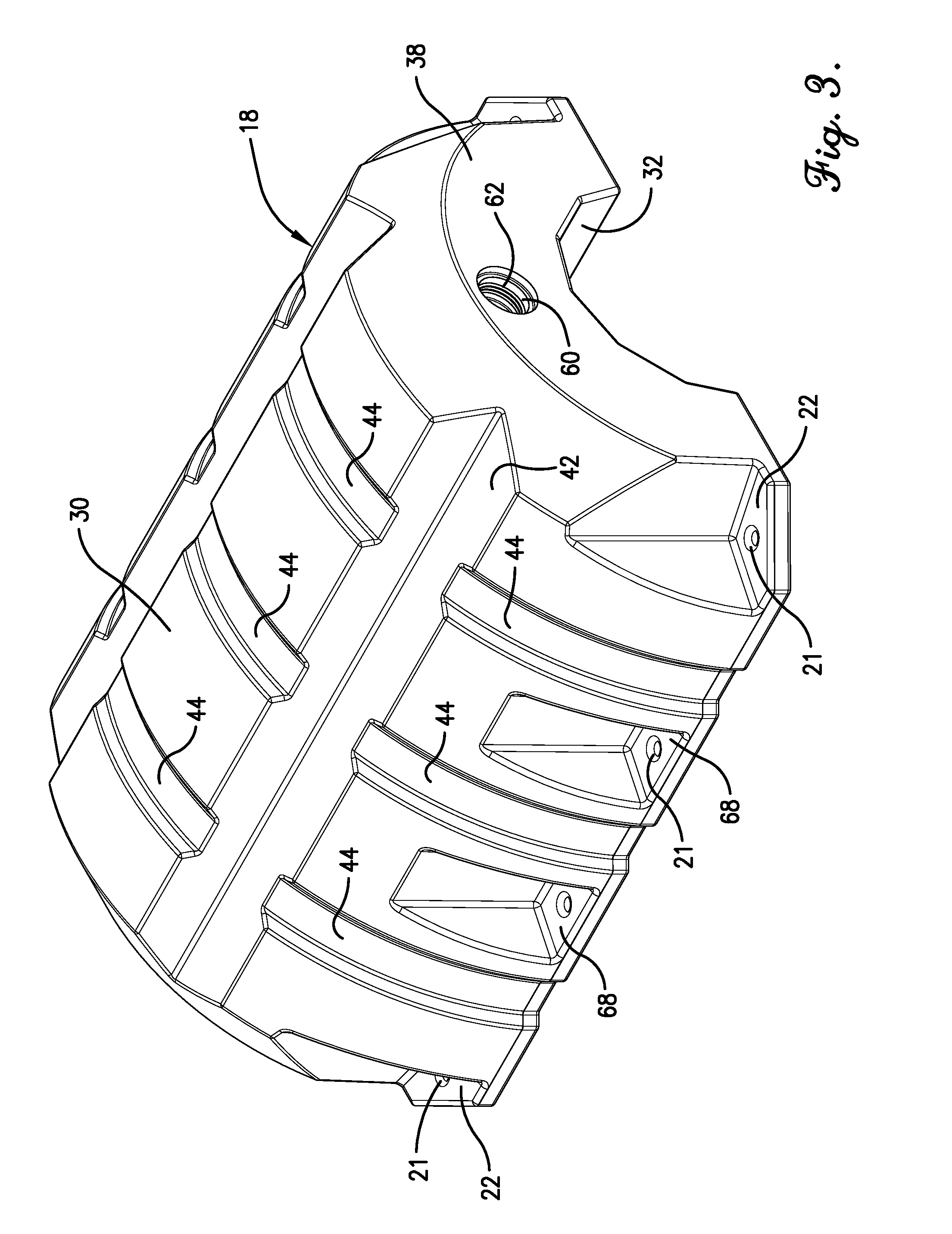
[0017]The pipe floats 10 are comprised of two pipe float sections 18, which in FIGS. 2, 5 and 6 are shown as pipe float sections 18A and 18B. In FIGS. 2 and 5, the pipe float sections 18A and 18B are, held together by threaded fasteners 20 such as nuts and bolts which pass through holes 21 in flanges 22 located at the corners of each pipe float section 18, whereas in FIG. 6 the pipe float sections are shown in a stacked and partially nested orientation for transport and storage. Advantageously, the pipe float sections 18A and 18B are identical in configuration and thus provide significant economies in manufacture and reduction of inventory while in transport or storage. When the pipe float sections...


PUM


Abstract

A pipe float is configured for receiving a pipe therein and providing buoyancy for maintaining the pipe along the surface of a body of water. The pipe float has an inner surface presenting a central passage adapted for receiving the pipe, the inner surface including a plurality of preferably substantially planar, longitudinally extending panels which provide a continuous inner surface. Adjacent panels are angularly oriented relative to one another, and the pipe float is preferably provided as a plurality of pipe float sections assembled together whereby one panel of a pipe float section is preferably oriented at an obtuse angle to an adjacent panel of that pipe float section. The panels may be of different transverse dimensions whereby the passage has a greater transverse dimension G which is substantially greater than a smaller transverse dimension S, with the outer diameter D of the pipe received in the passage being of a value equal to or smaller than G and greater than or equal to S.

Description

RELATED APPLICATIONS[0001]This is a continuation of U.S. application Ser. No. 13 / 783,152, filed Mar. 1, 2013, entitled PIPE FLOAT which in turn claimed priority to U.S. Provisional Application Ser. No. 61 / 615,116, filed Mar. 23, 2012, the earlier filed non-provisional application is hereby incorporated by reference into the present application in its entirety.[0002]This application claims the benefit of U.S. Provisional Patent Application No. 61 / 615,116 filed Mar. 23, 2012, the entire disclosure of which is incorporated herein by reference.BACKGROUND[0003]1. Field of the Invention[0004]The present invention concerns a pipe float adapted for attachment to a pipe or other enlongated members to provide buoyancy and maintain the portion of the pipe to which the float is attached at the surface of a body of water. The pipe float hereof is preferably configured with an internal surface having a plurality of planar faces to provide improved engagement with a typically cylindrical surface, ...

Claims


Application Information

Patent Timeline
IPC IPC(8): F16L1/24F16L1/20
CPCF16L1/20F16L1/24
Inventor MELYMUK, MICHAEL C.SKINNER, WILLIAM JAYEITZMANN, NICHOLAS L.
Owner SECURITY PAKS INT LLC D B A SPI PROD
Why Eureka
Try Eureka