Method for directed self-assembly (DSA) of a block copolymer (BCP) using a topographic pattern

Inactive Publication Date: 2016-11-24
WESTERN DIGITAL TECH INC
View PDF0 Cites 6 Cited by
  • Summary
  • Abstract
  • Description
  • Claims
  • Application Information

AI Technical Summary

Benefits of technology

[0009]In a second embodiment a conventional lithography process is used to generate a topographic pattern whose guiding features are only slightly higher than the interspatial trenches. In the first DSA step, an ultrathin film of a BCP blend with functional homopolymers is used. Since the height of the topographic features is comparable to the BCP film thickness, a typical graphoepitaxy DSA still occurs. Similarly, a 1:1 chemical pattern forms in the trenches. The ultrathin BCP film is then stripped. This new pattern will be acceptable for a second DSA of a BCP layer with a thickness of typically greater than L0. Since the second BCP film thickness is much larger than the height of the initial topographic features, the second BCP film also covers the topographic features and thus this new pattern works like a chemical pattern. Thus, DSA over the whole patterned area can be achieved. After removal of one of the

Problems solved by technology

Therefore, valuable area is lost

Method used


Image

  • Method for directed self-assembly (DSA) of a block copolymer (BCP) using a topographic pattern
  • Method for directed self-assembly (DSA) of a block copolymer (BCP) using a topographic pattern
  • Method for directed self-assembly (DSA) of a block copolymer (BCP) using a topographic pattern

Examples


first embodiment

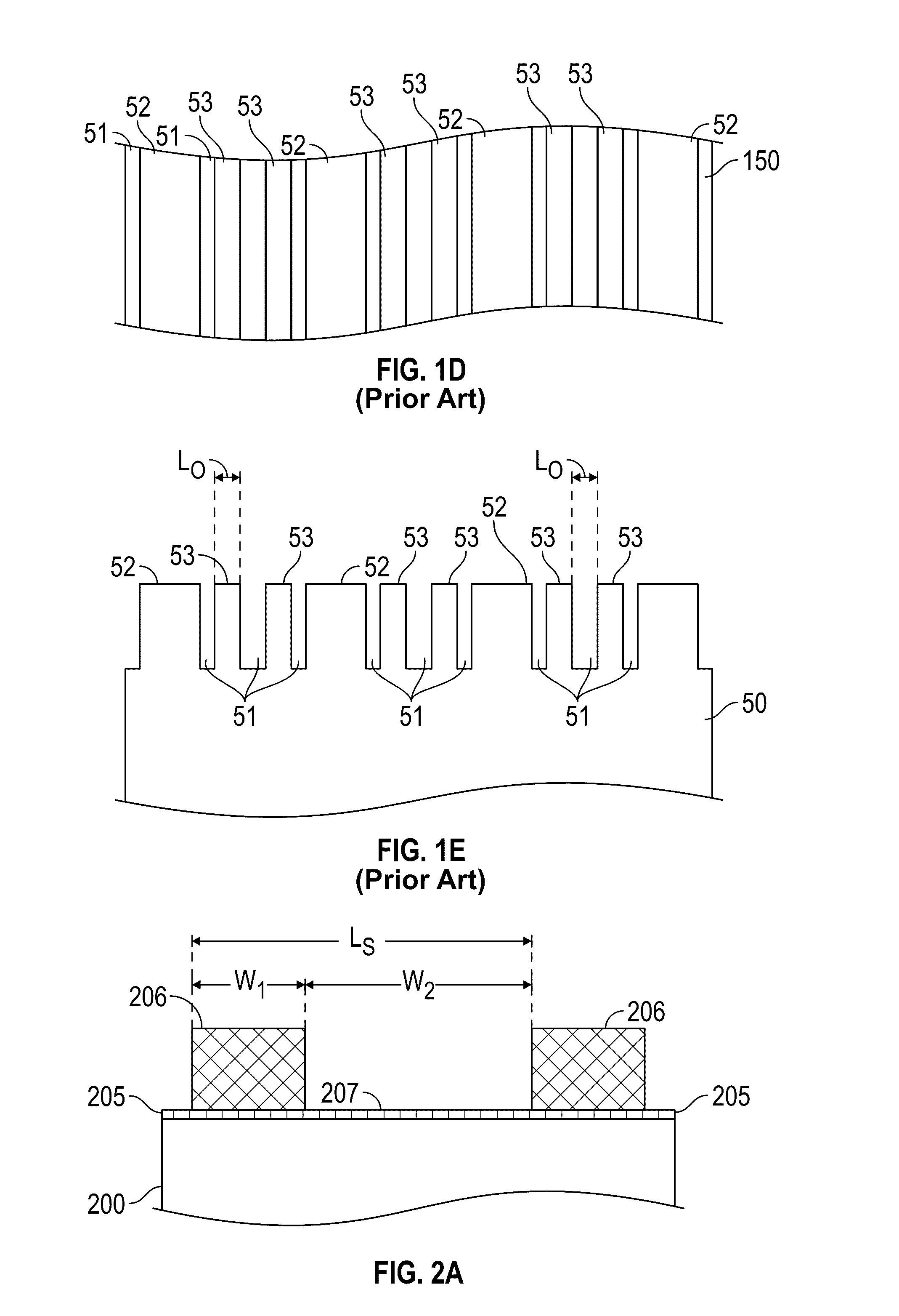
[0026]Embodiments of the method of this invention use intermediate steps between formation of the topographic pattern and deposition of the BCP and thus replace the prior art method illustrated and described above with respect to FIGS. 1A-1E. the invention is illustrated in FIGS. 2A-2H for an example where the BCP is poly(styrene-block-methyl methacrylate) (PS-b-PMMA) with L0=27 nm.

[0027]FIG. 2A is a perspective view of a substrate 200 with a patterned sublayer 205 that acts as a topographic pattern. The substrate 200 may be formed of any suitable material, such as, but not limited to, silicon-on-insulator (SOI), single-crystal Si, amorphous Si, silica, fused quartz, silicon nitride, carbon, tantalum, molybdenum, chromium, alumina and sapphire. The substrate may also be an intermediate layer formed on a semiconductor wafer or SOI base, such as an amorphous carbon layer or a silicon nitride (SiN) layer. The previously-cited Tsai et al. article describes the use of DSA to form a BCP p...

second embodiment

[0038]the invention is illustrated in FIGS. 3A-3H for an example where the BCP is poly(styrene-block-methyl methacrylate) (PS-b-PMMA) with L0=27 nm. Referring to FIG. 3A, a layer 305 of material with a thickness of 5-15 nm is formed on substrate 200. The material for layer 305 may be any of the materials used for stripes 206, but is preferably a neutral PS-r-PMMA mat. Then, in FIG. 3B an e-beam resist or photoresist layer is deposited on the layer 305 and e-beam lithography or photolithography is utilized to generate grating patterns of resist stripes 304 with a stripe pitch Ls=(m+n)L0. The resist pattern is then exposed to oxygen plasma etching so that the exposed portions of layer 305 are etched away, leaving stripes 306. This also oxidizes the sidewalls of the stripes 306. The remaining resist pattern is rinsed away in a suitable solvent (e.g., toluene, PGMA, or NMP), leaving the structure as shown in FIG. 3C with stripes 306 with a stripe pitch Ls=(m+n)L0. The width of the resul...


PUM


Abstract

A method uses a topographic pattern for directed self-assembly (DSA) of block copolymers (BCPs). Conventional lithography generates a topographic pattern of guiding stripes that have sidewalls that preferentially wet one of the blocks. A BCP blend with functional homopolymers, called “inks”, is deposited and annealed on the topographic pattern. After annealing, the BCP blend is guided to self-assemble by the topographic pattern. The inks selectively distribute into blocks, and part of the inks graft in the trenches between the topographic features. The BCP blend layer is rinsed away, leaving the grafted inks that form a chemical pattern. A second layer of BCP is deposited on this chemical pattern and annealed, resulting in DSA of the second BCP. After removal of one of the BCP blocks of the second BCP, the remaining blocks can serve as an etch mask.

Description

BACKGROUND OF THE INVENTION[0001]1. Field of the Invention[0002]This invention relates generally to the directed self-assembly (DSA) of block copolymers (BCPs), and more particularly to the DSA of BCPs using a topographic pattern as a patterned sublayer.[0003]2. Description of the Related Art[0004]Block copolymer (BCP) patterns are useful and viable alternatives for patterning at dimensions not achievable by conventional lithographic processes. Thin films of block copolymers (BCPs) self-assemble at dimensions in the range of 5-50 nm, making them very attractive for lithographic applications. BCPs are polymeric chains with two or more incompatible blocks joined by covalent bonds. By annealing the polymer above its glass transition temperature (Tg) the polymer chains gain enough mobility to diffuse. The strength of the incompatibility between the blocks will drive the system towards an equilibrium morphology which results in periodic, uniform patterns with a periodicity or natural pit...

Claims


Application Information

Patent Timeline
IPC IPC(8): G03F7/16B05D1/38B05D3/10B05D1/32
CPCG03F7/165B05D3/107B05D1/38B05D1/32G03F7/0002
Inventor RUIZ, RICARDOWAN, LEI
Owner WESTERN DIGITAL TECH INC
Why Eureka
Try Eureka