
Limited ozone generator transfer device

Inactive Publication Date: 2012-08-23
XEROX CORP
View PDF5 Cites 0 Cited by
  • Summary
  • Abstract
  • Description
  • Claims
  • Application Information

AI Technical Summary

Benefits of technology

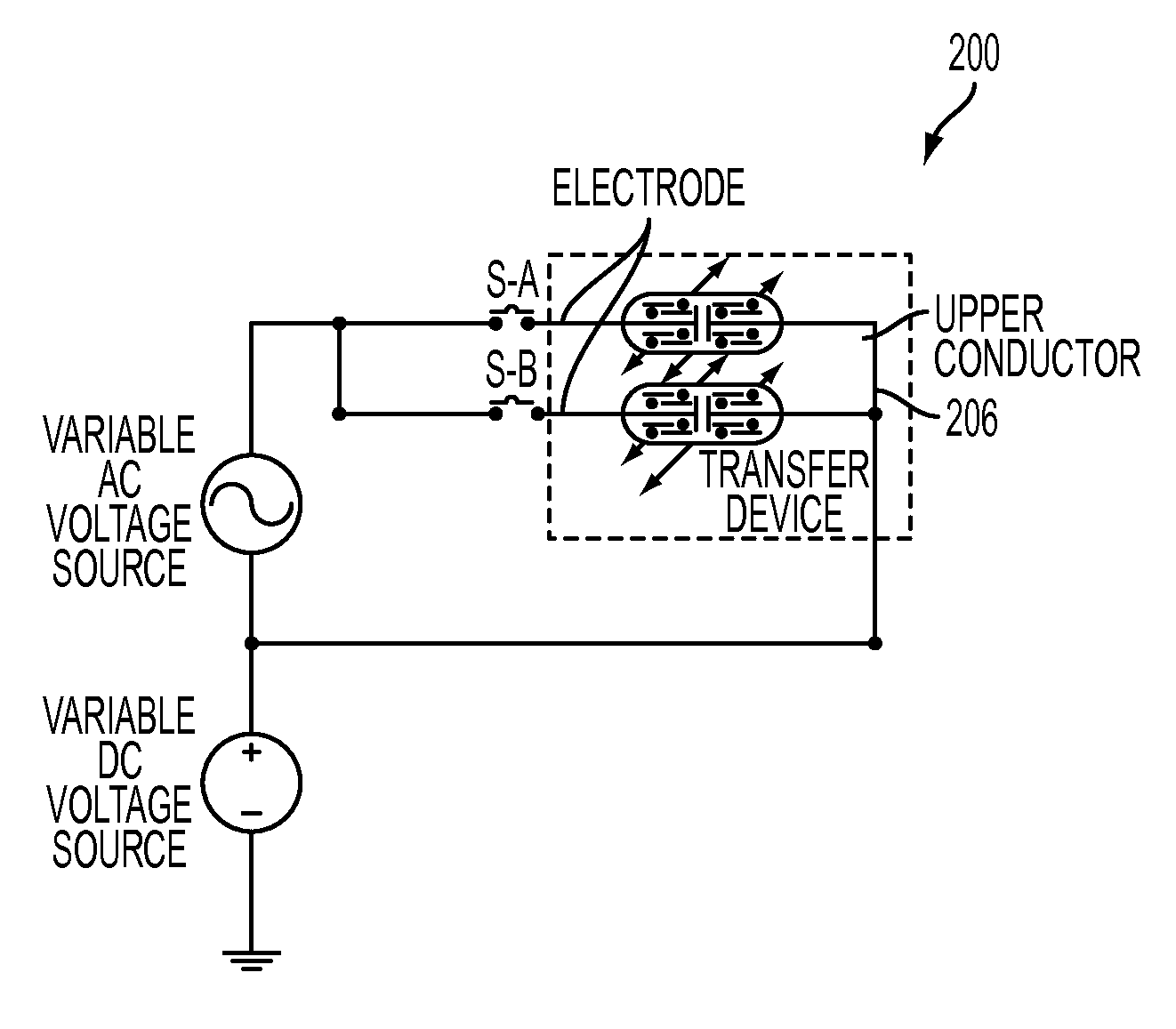
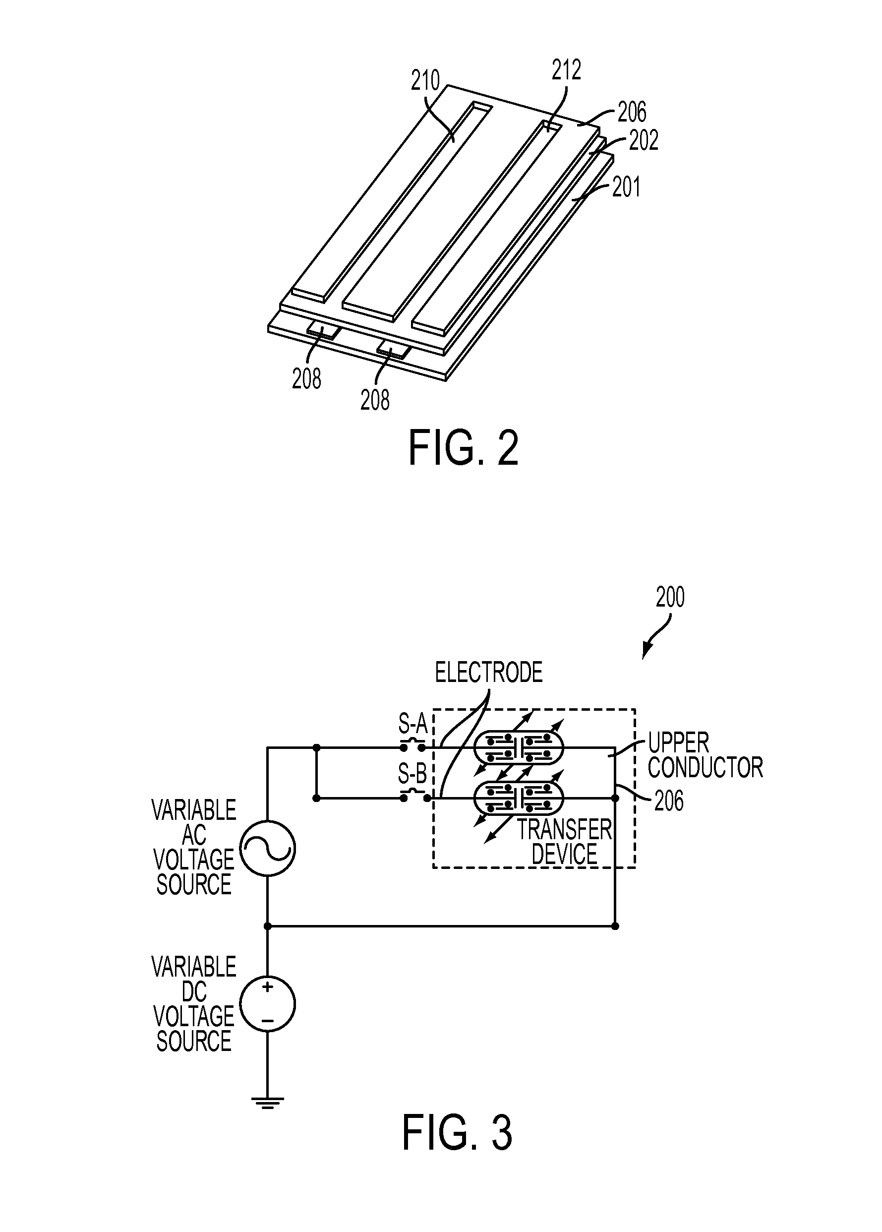
[0009]In answer to this need, provided hereinafter is a limited ozone generator transfer device that includes sequential layers of a ceramic substrate, conducting lines, a dielectric layer, and a top conducting layer having slots therein that align with the underlying conducting lines. Corona is generated in the slots by applying an AC voltage of about 2.5 kVp-p across the dielectric. This device is “green” in that it generates significantly less ozone than conventional transfer devices, thus reducing the requirements on the ozone collection system.

Problems solved by technology

Removal of this ozone has traditionally been done utilizing extensive air handling systems that add additional cost into the printer.

Method used


Image

  • Limited ozone generator transfer device
  • Limited ozone generator transfer device
  • Limited ozone generator transfer device

Examples


Embodiment Construction

[0019]While the disclosure will be described hereinafter in connection with a preferred embodiment thereof, it will be understood that limiting the disclosure to that embodiment is not intended. On the contrary, it is intended to cover all alternatives, modifications and equivalents as may be included within the spirit and scope of the disclosure as defined by the appended claims.

[0020]The disclosure will now be described by reference to a preferred embodiment xerographic printing apparatus that includes a method and apparatus for limiting ozone creation while transferring toner to a media.

[0021]For a general understanding of the features of the disclosure, reference is made to the drawings. In the drawings, like reference numerals have been used throughout to identify identical elements.

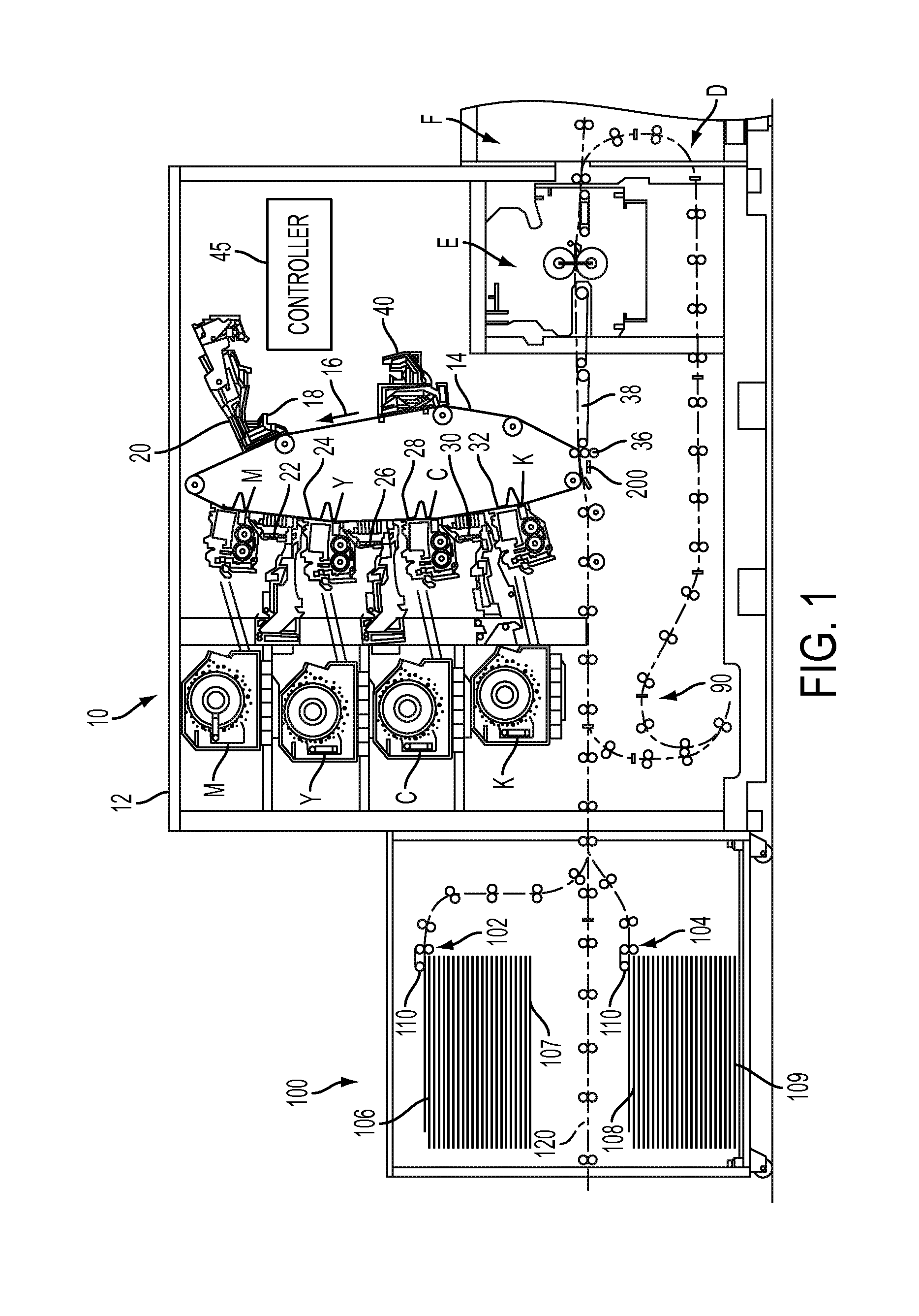
[0022]Referring now to printer 10 in the figure, as in other xerographic machines, and as is well known, shows an electrographic printing system including the improved method and apparatus for reduc...


PUM


Abstract

A limited ozone generator transfer device includes a ceramic substrate having conducting lines, a dielectric layer, and a top conducting layer with slots therein that align with the underlying conducting lines. Corona is generated in the slots by applying an AC voltage of about 2.5 kVp-p across the electrodes. This device is “green” in that it generates significantly less ozone than conventional transfer devices, thus reducing requirements on an ozone collection system.

Description

BACKGROUND[0001]1. Field of the Disclosure[0002]The present disclosure relates generally to a system for transfer of charged toner particles in an electrostatographic printing apparatus, and more particularly, concerns a non-contact limited ozone producing transfer device used in such a machine.[0003]2. Description of Related Art[0004]Typically, in an electrostatographic printing process of printers, such as, U.S. Pat. No. 6,033,452, which is incorporated herein by reference to the extent necessary to practice the present disclosure, a photoconductive member is charged to a substantially uniform potential so as to sensitize the surface thereof. The charged portion of the photoconductive member is exposed to selectively dissipate the charges thereon in the irradiated areas. This records an electrostatic latent image on the photoconductive member. After the electrostatic latent image is recorded on the photoconductive member, the latent image is developed by bringing a developer mater...

Claims


Application Information

Patent Timeline
IPC IPC(8): G03G15/16
CPCG03G15/1635
Inventor DALOIA, GERALD F.DOODY, MICHAEL A.BARROSO, DANIEL
Owner XEROX CORP
Learn More