Method and system for detecting a flow blockage in a pipe

a flow blockage and detection method technology, applied in fluid pressure measurement, instruments, machines/engines, etc., can solve the problem that the pipe through which the pressure measurement is carried out has become blocked with ice, and achieve the effect of simple and robust technique and readily detect the blockage of the p30 sensor pip

Active Publication Date: 2015-08-06
ROLLS ROYCE PLC
View PDF4 Cites 7 Cited by
  • Summary
  • Abstract
  • Description
  • Claims
  • Application Information

AI Technical Summary

Benefits of technology

[0025]The method of the invention provides a simple and robust technique for detecting the presence of the variations in the value of the P30 sensor signal with time, which in turn allow an operator to readily detect a blockage in the P30 sensor pipe.
[0026]The method and system of the invention enable a flow blockage of the P30 sensor pipe to be detected within seconds rather than at the point at which the engine conditions changes. This enables the engine to be immediately and automatically switched into modelled P30 mode. Thus any thrust anomalies would be avoided altogether and thus a potential safety issue removed. The pilot warning is given when he is otherwise unoccupied and does not add to his workload during an aircraft manoeuvre.

Problems solved by technology

Consequently, the lack of variation in this signal indicates that the pipe through which this pressure is measured has become blocked with ice.

Method used


Image

  • Method and system for detecting a flow blockage in a pipe
  • Method and system for detecting a flow blockage in a pipe
  • Method and system for detecting a flow blockage in a pipe

Examples


Embodiment Construction

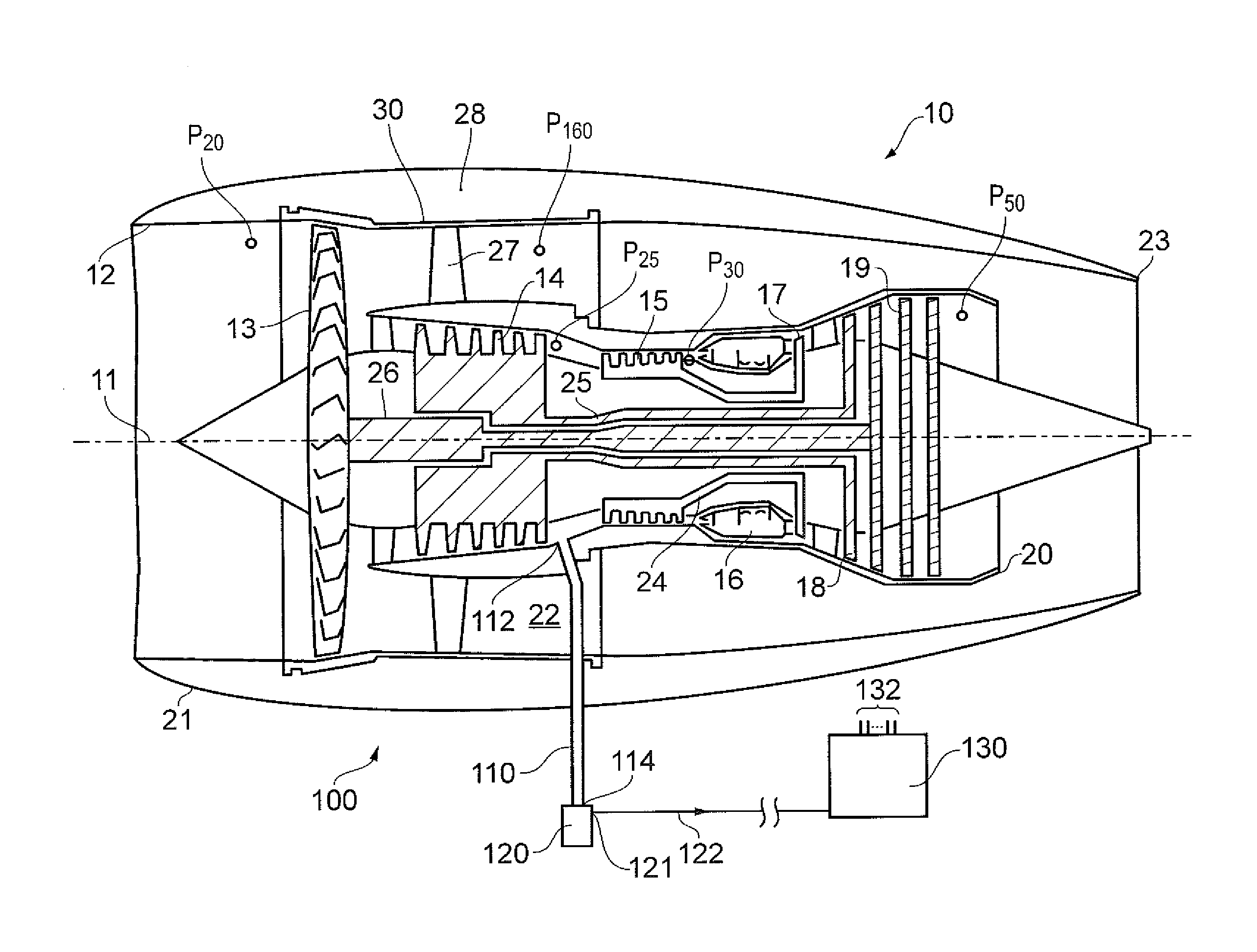
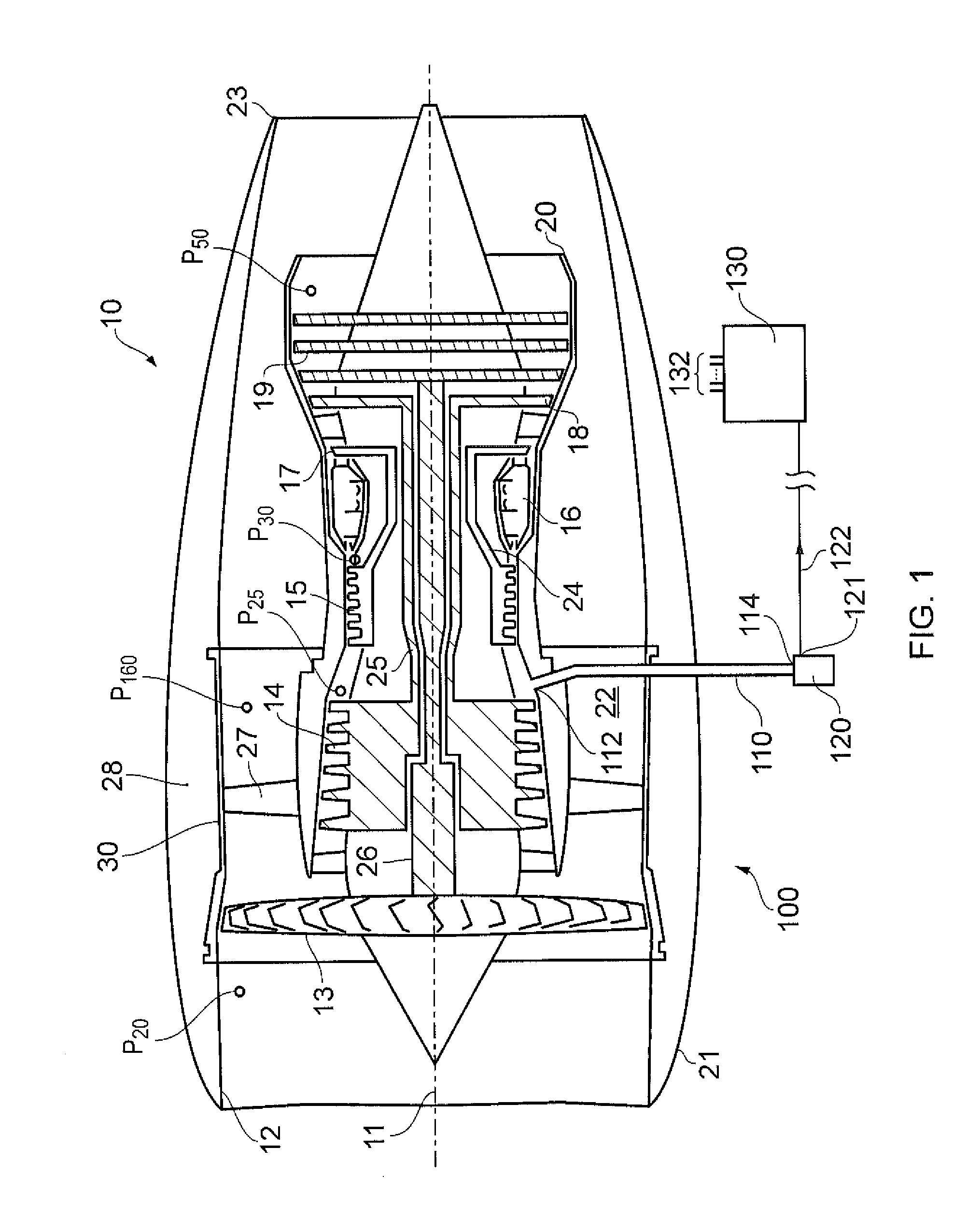
[0059]Referring to FIG. 1, a system according to the invention is designated generally by the reference numeral 100.

[0060]The system 100 comprises a pressure signal pipe 110, a pressure sensor 120 and a processor 130. In the arrangement of FIG. 1, the system 100 is shown as part of a turbofan engine 10 for an aircraft application.

[0061]The pressure signal pipe 110 is connected at a first end 112 to the outlet of the high pressure compressor 15 of the gas turbine engine 10, and at a second end 114 to the pressure sensor 120. The pressure sensor 120 is thus in fluid communication with the outlet of the high pressure compressor 15 of the gas turbine engine 10 and corresponds to the P30 signal pipe.

[0062]In the arrangement shown in FIG. 1 the pressure sensor 120 is shown as being situated external to the nacelle 21 of the engine 10. In alternative arrangements the pressure sensor 120 may be situated within the nacelle 21, for example within the void 28 created between the nacelle 21 and...


PUM

PropertyMeasurementUnit
frequencyaaaaaaaaaa
frequencyaaaaaaaaaa
frequencyaaaaaaaaaa

Abstract

A method of detecting a flow blockage in a pipe includes: arranging a fluid flow along the pipe, the pipe in fluid communication with a pressure sensor; configuring the pressure sensor to measure a pressure within the pipe; recording plurality of measurements of pressure within the pipe; sampling ‘n’ successive values of pressure within the pipe; performing an analytical test on the ‘n’ successive values, the analytical test producing an output value, the output value representative of a variation in the individual ones of the ‘n’ successive values; comparing the output value to a pre-defined threshold value, the threshold value indicative of a lack of variation in the individual ones of the ‘n’ successive values; and if the output value is less than the threshold value, generating an alert to provide a user with an indication of the presence of flow blockage in the pipe.

Description

This invention claims the benefit of UK Patent Application No. 1401928.5, filed on 5 Feb. 2014, which is hereby incorporated herein in its entirety.FIELD OF THE INVENTION[0001]The present invention relates to a method of detecting a flow blockage in a pipe and particularly, but not exclusively, to a method of detecting a flow blockage in a gas pressure signal pipe.BACKGROUND TO THE INVENTION[0002]With reference to FIG. 1, a conventional high bypass ratio turbofan engine generally indicated at 10 has a principal and rotational axis 11. This turbofan engine comprises a three-shaft gas turbine engine having high, intermediate and low pressure spools. Such engines are typically provided with a single rotating stage in both the high and intermediate turbines. The low pressure turbine however, usually comprises many stages.[0003]The engine 10 comprises, in axial flow series, an air intake 12, a propulsive fan 13, an intermediate pressure compressor 14, a high pressure compressor 15, combu...

Claims


Application Information

Patent Timeline
Patent Type & Authority Applications(United States)
IPC IPC(8): G01L19/08
CPCG01L19/083F17C2265/068F05D2260/80F05D2210/12F17D3/00F17D3/01F17D3/18F17D5/00F17D5/005F17D5/02F17C2221/031F17C2223/0123F17C2250/043F17C2250/0694F17C2250/072F05D2270/71F05D2270/803F01D17/08G01L19/12F02K1/00
Inventor GRICE, CHRISTOPHER MICHAEL
Owner ROLLS ROYCE PLC
Why Eureka
Try Eureka