Leaky wave antenna in AFSIW technology

Active Publication Date: 2021-06-17
THALES SA +3
View PDF0 Cites 2 Cited by
  • Summary
  • Abstract
  • Description
  • Claims
  • Application Information

AI Technical Summary

Benefits of technology

The invention aims to provide a solution for creating antennas on small substrates that have superior performance levels in terms of radiating pattern and limited dielectric losses. The invention uses a special technology called AFSIW waveguides, which allows for the production of leaky waveguides that are smaller, lighter, and cheaper than traditional antennas, while still maintaining good performance levels. This technology uses simple and robust manufacturing techniques to create efficient and effective antennas.

Problems solved by technology

Such antennas are however difficult to manufacture and costly because of the issue of assembly and production accuracy.
However, the slotted antennas, produced by implementing this technology have the known drawback of exhibiting significant dielectric losses.
Moreover, overdimensioning the amplification functions is reflected by an increase in the energy consumption of the system.

Method used


Image

  • Leaky wave antenna in AFSIW technology
  • Leaky wave antenna in AFSIW technology
  • Leaky wave antenna in AFSIW technology

Examples


Embodiment Construction

[0038]The recently developed air-filled substrate integrated waveguide (AFSIW) technology has only recently been used to produce guided transmission lines on a substrate. Hereinafter in the text, such a structure is qualified as “AFSIW waveguide”.

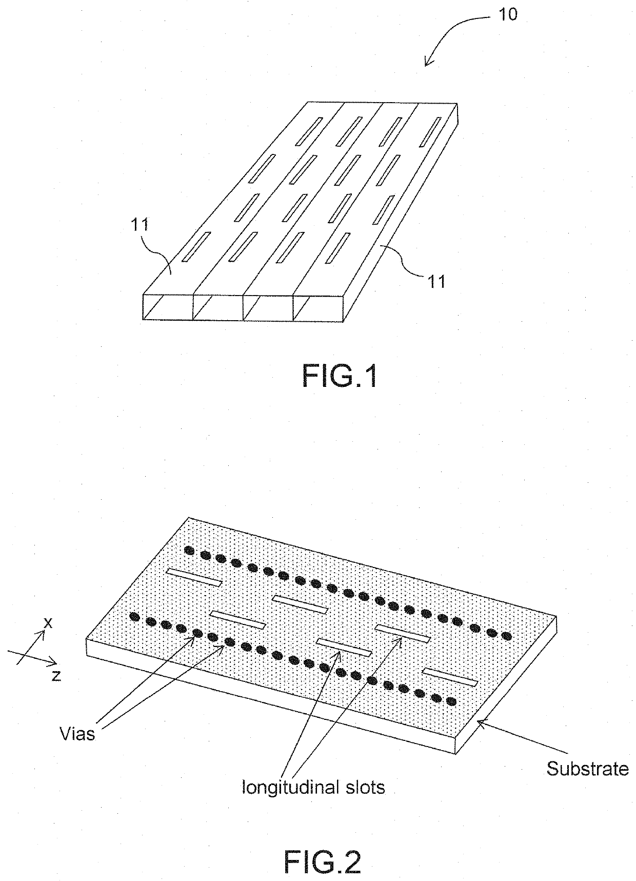
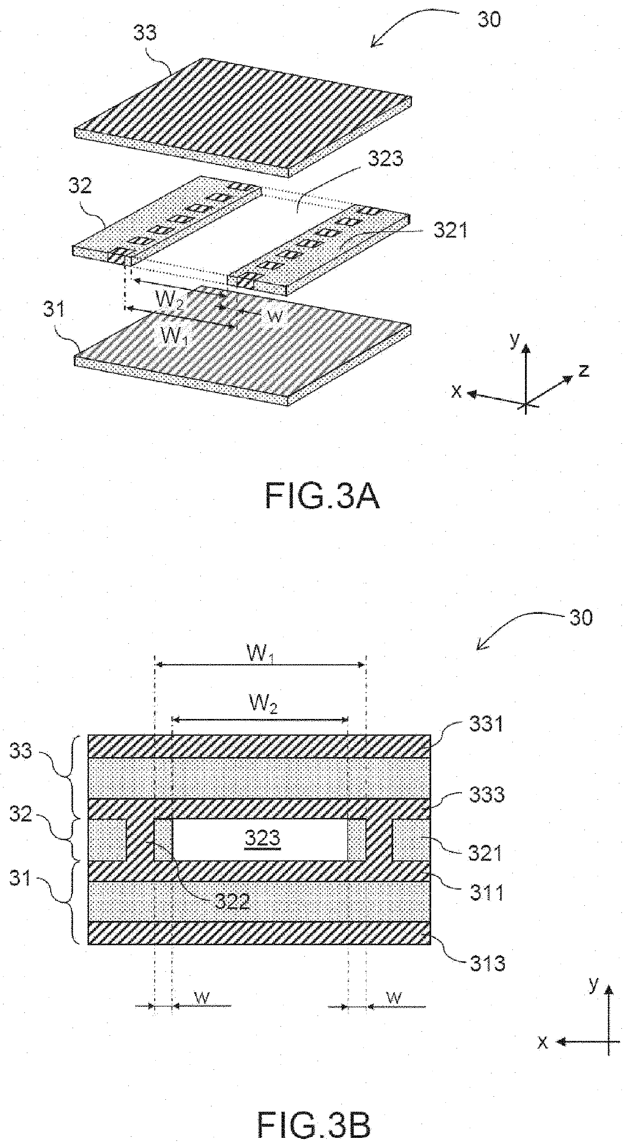
[0039]This technology advantageously allows guided transmission lines to be obtained that exhibit enhanced performance levels, notably in terms of dielectric losses, compared to the structures in SIW technology used hitherto, structures illustrated by FIG. 2.

[0040]Compared to the structures of metal waveguide type, illustrated by FIG. 1, such transmission lines also exhibit advantageous characteristics in terms of weight and bulk.

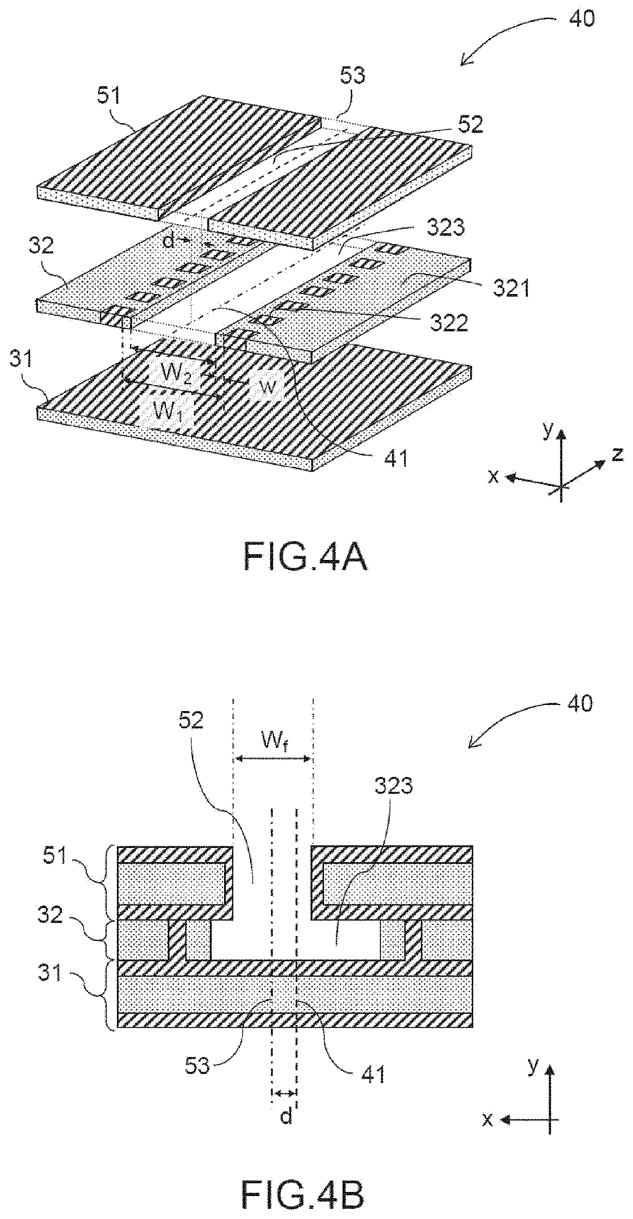
[0041]From the technological point of view, the leaky wave antenna according to the invention relies on the AFSIW waveguide production technology.

[0042]As FIGS. 3A and 3B, profile view and a cross-sectional view respectively, illustrate, the structure of an AFSIW waveguide comprises three dielectric substrate layer...


PUM


Abstract

Leaky wave antenna of AFSIW structure comprising a top substrate layer and a bottom substrate layer sandwiching an intermediate layer comprising a longitudinal aperture of length L defining a waveguide and whose width W1 is delimited by two conductive lateral walls. The inner faces of the conductive lateral walls are coated with a layer of dielectric material of thickness w(z). The top layer has a longitudinal radiating slot of width Wf (z) facing the longitudinal aperture of the intermediate layer. The thickness w(z) of the dielectric coating varies along the longitudinal axis z according to a given law, defined so as to obtain variations along the axis z of the amplitude Alpha(z) and of the phase Beta(z) of the leaky wave of the guide.

Description

FIELD OF THE INVENTION[0001]The present application claims priority to French Application No. 1914577 filed with the Intellectual Property Office of France on Dec. 17, 2019 which is incorporated herein by reference in its entirety for all purposes.FIELD OF THE INVENTION[0002]The invention relates to the general field of microwave antennas used in radars and telecommunications. It relates more particularly to the field of array antennas or leaky wave antennas.CONTEXT OF THE INVENTION—PRIOR ART[0003]The leaky wave antennas in metallic waveguide technology are broadly described in the literature. FIG. 1 presents an outline illustration of the principle of production of such an antenna 10 by means of slotted waveguides 11.[0004]Such antennas are however difficult to manufacture and costly because of the issue of assembly and production accuracy.[0005]In order to reduce the manufacturing costs and obtain integrated leaky wave antennas, it is also known practice to implement the substrate...

Claims


Application Information

Patent Timeline
IPC IPC(8): H01Q13/22H01Q13/28
CPCH01Q13/22H01Q13/28H01Q13/20
Inventor GHIOTTO, ANTHONYRAIMOND, RYANMAZEAU, THIERRY
Owner THALES SA
Why Eureka
Try Eureka