
Receiving device

a technology of receiving device and receiver, which is applied in the direction of receiving monitoring, pilot signal control, transmission monitoring, etc., can solve the problems of signal detection accuracy degradation, unsuitable standby gain in wireless communication device, and degraded signal detection accuracy, so as to suppress the degradation of detection accuracy and speed up the speed of convergence of agc processing

Active Publication Date: 2015-08-06
PANASONIC CORP
View PDF0 Cites 15 Cited by
  • Summary
  • Abstract
  • Description
  • Claims
  • Application Information

AI Technical Summary

Benefits of technology

This patent is about a receiving device that improves the speed at which it adjusts for changes in signal strength and maintains the accuracy of the detection, even if the device that it is connected to changes or moves. This means that the device is more efficient and reliable, regardless of the circumstances in which it is used.

Problems solved by technology

Therefore, there is a problem in that it takes time for AGC to converge for a signal arriving from the distant terminal B, signal demodulation is delayed, and the signal detection accuracy is degraded.
In addition, when the terminal A is moved, the standby gain in the wireless communication device becomes unsuitable.
Therefore, there is also a problem in that it takes time for AGC to converge, signal demodulation is delayed, and the signal detection accuracy is degraded.

Method used


Image

  • Receiving device
  • Receiving device
  • Receiving device

Examples


Embodiment Construction

[0027]An embodiment of a receiving device according to the present disclosure (referred to below as the “present embodiment”) will now be described with reference to the drawings. The receiving device of the present embodiment is an information communication terminal that complies with wireless LAN communication specifications (for example, IEEE 802.11ad), and is, for example, a smartphone or tablet terminal. However, the receiving device of the present embodiment is not limited to a smartphone or tablet terminal.

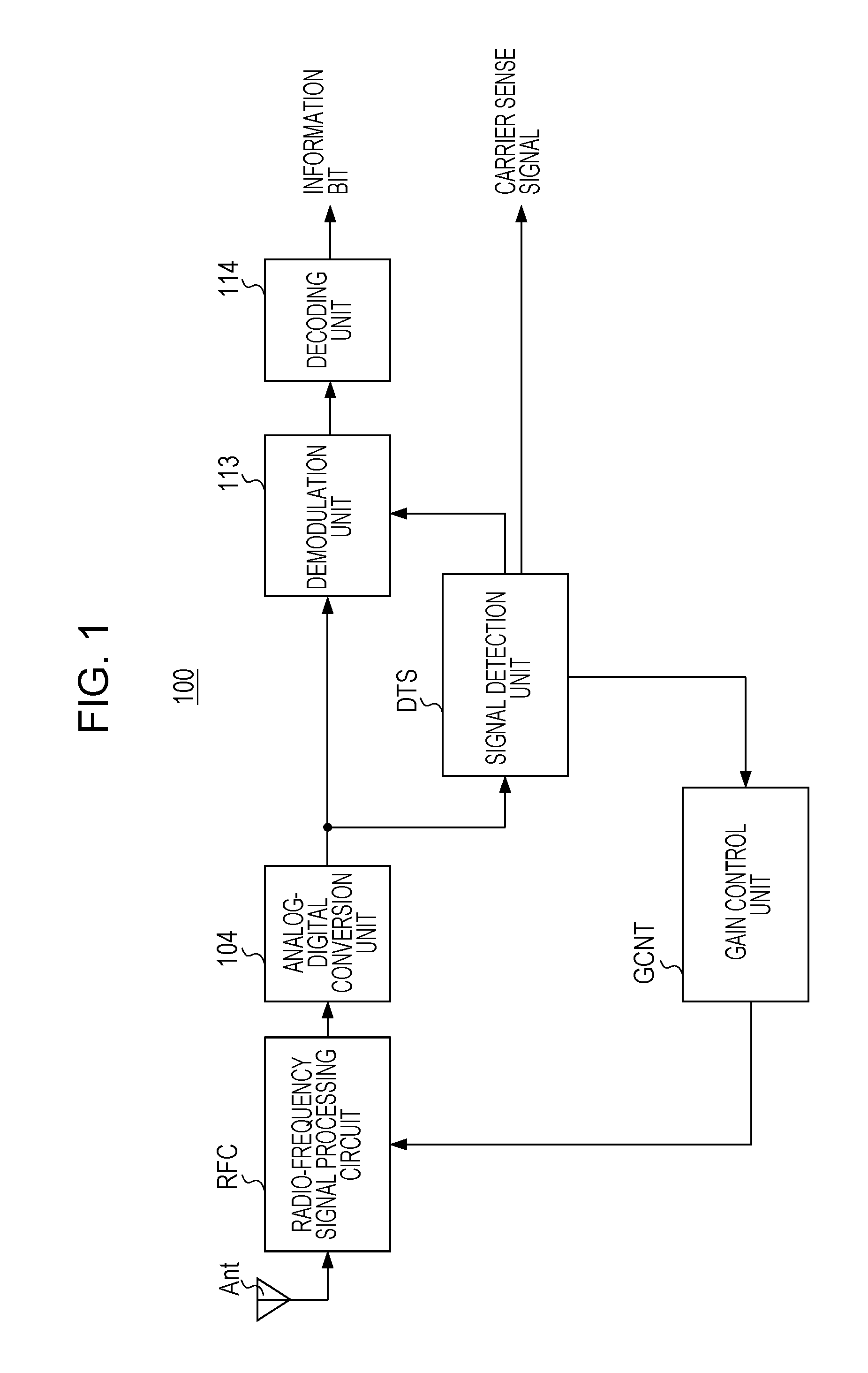
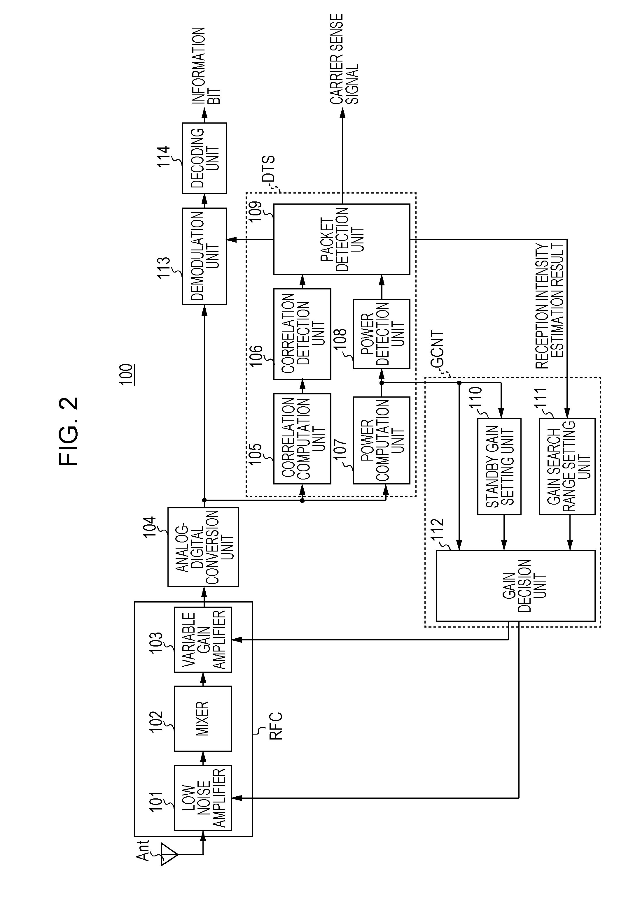
[0028]FIG. 1 is a block diagram schematically illustrating an internal configuration of a receiving device 100 of the present embodiment. FIG. 2 is a block diagram illustrating in detail the internal configuration of the receiving device 100 of the present embodiment. The receiving device 100 illustrated in FIG. 1 includes a radio-frequency signal processing circuit RFC to which a receiving antenna Ant is connected, an analog-digital conversion unit 104, a signal detection ...


PUM


Abstract

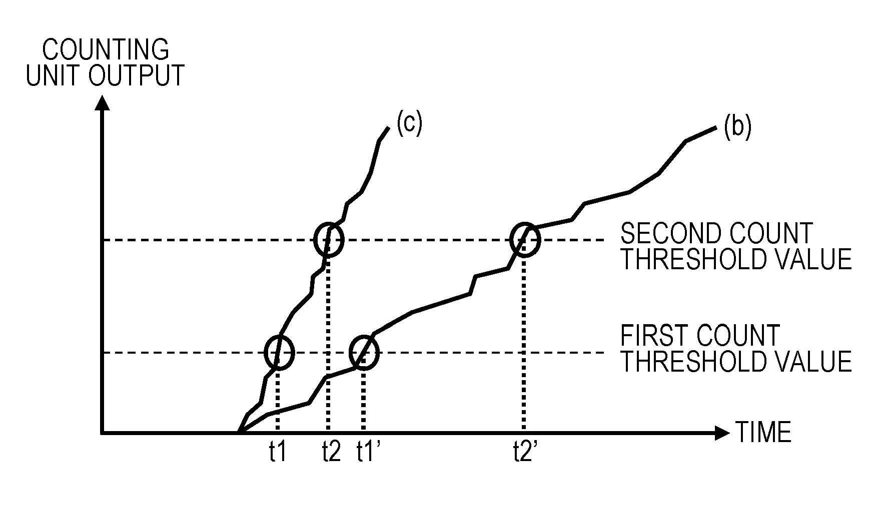
A receiving device that receives a signal in a receiving antenna. The receiving device includes a gain controller that adjusts a gain in the receiving device in response to information related to power of the signal, and a signal detector that determines whether, within a predetermined period after the information related to the power of the signal exceeds a first threshold value, the information related to the power of the signal exceeds a second threshold value which is larger than the first threshold value. The gain controller adjusts a search range of the gain in the receiving device based on a determination result of the signal detector with respect to the information related to the power of the signal.

Description

CROSS REFERENCES TO RELATED APPLICATIONS[0001]This application claims priority to Japanese Patent Application No. 2014-020660, filed on Feb. 5, 2014, the contents of which are hereby incorporated by reference.BACKGROUND[0002]1. Technical Field[0003]The present disclosure relates to a receiving device that controls a gain in response to power of a received signal.[0004]2. Description of the Related Art[0005]For wireless local area networks (LANs), the standardization of, for example, the Institute of Electrical and Electronics Engineering, Inc. (IEEE) 802.11ad communication specifications has been promoted. In IEEE 802.11ad, an access control method referred to as carrier sense multiple access / collision avoidance (CSMA / CA) has been adopted.[0006]In CSMA / CA, a receiving device detects a signal existing in a wireless transmission path, and adjusts a gain for amplifying the detected signal such that a fluctuation range of the detected signal falls within a dynamic range of an analog-dig...

Claims


Application Information

Patent Timeline
Patent Type & Authority Applications(United States)
IPC IPC(8): H04B17/21H04B1/16H03G3/30
CPCH04B17/21H04B1/16H03G3/3042H04B17/318H03G3/3052H03G3/3078H03G3/3036H03G3/005H04B1/1027
Inventor TANAKA, KOICHIROMOTOZUKA, HIROYUKIYOSOKU, NAOYA
Owner PANASONIC CORP
Learn More