Self-ligating orthodontic bracket

a self-ligating, orthodontic technology, applied in the field of self-ligating orthodontic brackets, can solve the problems of time and cost, introduce new difficulties and concerns, discoloration and stain, etc., to reduce the likelihood of any increase tensile strength, and reduce the likelihood of force being transferred to the patient's tooth

Inactive Publication Date: 2015-08-13
LANCER ORTHODONTICS
View PDF1 Cites 22 Cited by
  • Summary
  • Abstract
  • Description
  • Claims
  • Application Information

AI Technical Summary

Benefits of technology

[0010]In one embodiment, the ligating gate has multiple enhancements to ensure that the archwire is properly retained in the archwire slot and allows for passive archwire correction. The ligating gate has a lead-in radius on its leading edge so that as the gate moves from an open position toward a closed position, the lead-in radius will slide over the archwire in the archwire slot and push the archwire down to help seat the archwire in the slot. The gate has a top surface and a bottom surface, and the bottom surface includes a recess defined by symmetrical projecting edges extending around the outer perimeter of the bottom surface. The symmetrical projecting edges may come into contact with the archwire during adjustment periods, thereby providing mesial-distal contact at two contact points between the projecting edges and the archwire, which improves rotational control. The recess in the bottom of the gate extends at least partially over the archwire slot and provides clearance between the bottom of the gate and the archwire, which may allow for a shallower archwire slot.
[0012]In one embodiment, an orthodontic bracket includes a bracket body configured to be mounted on teeth and includes an archwire slot having a base, and a base surface, defining a base plane. An archwire is configured for mounting in the archwire slot. In this embodiment, a ligating gate has a top surface, a first side and a second side, and a bottom surface. A post extends outwardly from the bottom surface. A cavity surrounds the post in the bottom surface. Further, the bottom of the gate includes a recess with a recess perimeter extending around the recess. In this embodiment, a first retainer and a second retainer are formed on the bracket body and are used to retain the ligating gate on the bracket. As the ligating gate slides from an open position to a closed position, the first side and the second side of the gate slide within the first retainer and second retainer respectively, as a guide. There may be some frictional resistance between the gate and the first and second retainers when sliding the gate open or closed. A slot in the bracket body has an offset keyhole in the slot and is configured for receiving a post which extends from the bottom of the gate. During assembly of the gate into the first and second retainers, the post is inserted into the offset keyhole and the post then realeasably locks the gate in the open position. As the gate is moved from the open position to the closed position over the archwire slot, the post shifts out of the offset keyhole and slides along the slot thereby applying a slight frictional resistance between the post and the slot as the gate slides to the closed position. As the post in the bottom of the gate extends further along the slot as the gate is closed, the gate locks into place over the archwire slot due to the post engaging a slot opening at the end of the slot. In one embodiment, the post has a chamfer on its end, the chamfer facilitating insertion of the post into the slot when the gate is mounted on the bracket.
[0013]The self-ligating gate includes reciprocal opening force mechanics. Typically, self-ligating brackets require a load to be applied directly to the ligating member in order to open the ligating member from the closed position to the open position. This results in forces and moments of inertia applied to the patient's tooth, which can be very uncomfortable to the patient, and it may in fact debond the bracket from the tooth. With the present invention, reciprocal opening force mechanics result in all of the opening forces and moments of inertia be contained in the bracket structure and little to no forces are transmitted to the patient's tooth. This provides for a much more comfortable feel to the patient as the self-ligating gate is moved from the closed position to the open position. To open the gate, an opening tool, similar to a screwdriver, is placed between a bracket body vertical wall and the gate leading edge and rotated or twisted 90° to slide the gate from the closed position to the open position. All of the opening force mechanics are distributed to the bracket body vertical wall and the gate thereby reducing the likelihood of any forces being transferred to the patient's tooth.
[0014]In one embodiment, the orthodontic bracket body includes a debonding core which is essentially a recess or cavity extending into the bracket body. The debonding core provides the bracket body with a flexible structure to assist in debonding the bracket from the patient's tooth without causing discomfort to the patient, or injuring the enamel on the tooth. Further, there is a bond base made up of multiple projections that resist shear loading and increase tensile strength, while facilitating debonding the bracket at the end of treatment. In one embodiment, the spacing and surface area of the multiple projections emulates the surface area of an 80 gauge mesh which is known in the art to have superior bonding characteristics in clinical use.

Problems solved by technology

Since such a large portion of an orthodontic patient's time in the orthodontist's chair is consumed by changing archwires in this manner, and since such routine archwire changes constitute a major cost to the orthodontic practice and contribute to the cost of treatment for the patient, much inventive effort has gone into identifying innovative chairside systems that reduce the time and cost associated with archwire changing.
The use of elastomeric O-rings however introduce new difficulties and concerns.
For example, they can discolor and stain and they can lose their tractive force capabilities as they absorb water in the mouth.
In either case, any instruments for ligature placement must be sterilized after each use, thus requiring specific in-practice procedures which involve measurable cost.

Method used


Image

  • Self-ligating orthodontic bracket
  • Self-ligating orthodontic bracket
  • Self-ligating orthodontic bracket

Examples


Embodiment Construction

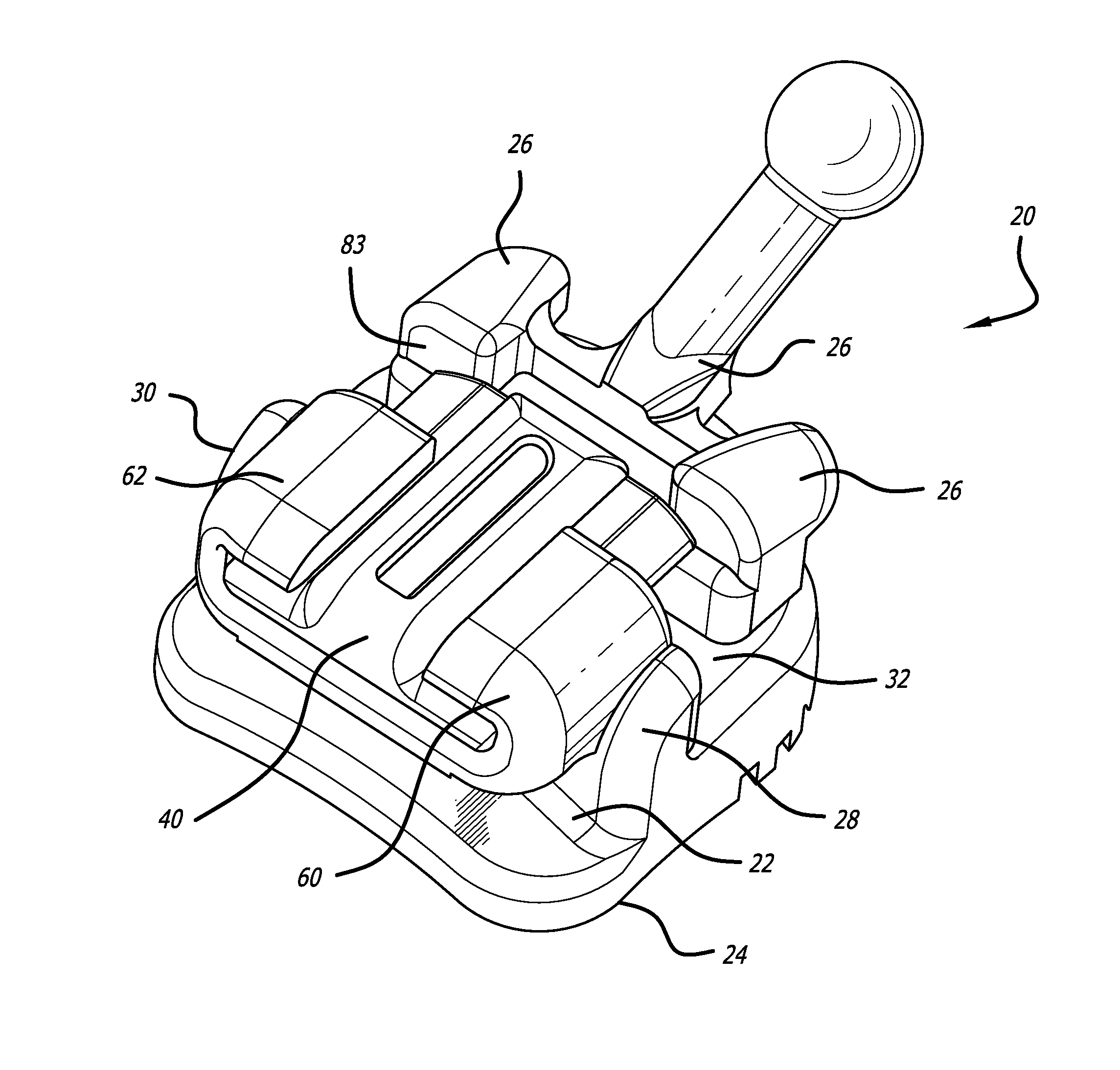
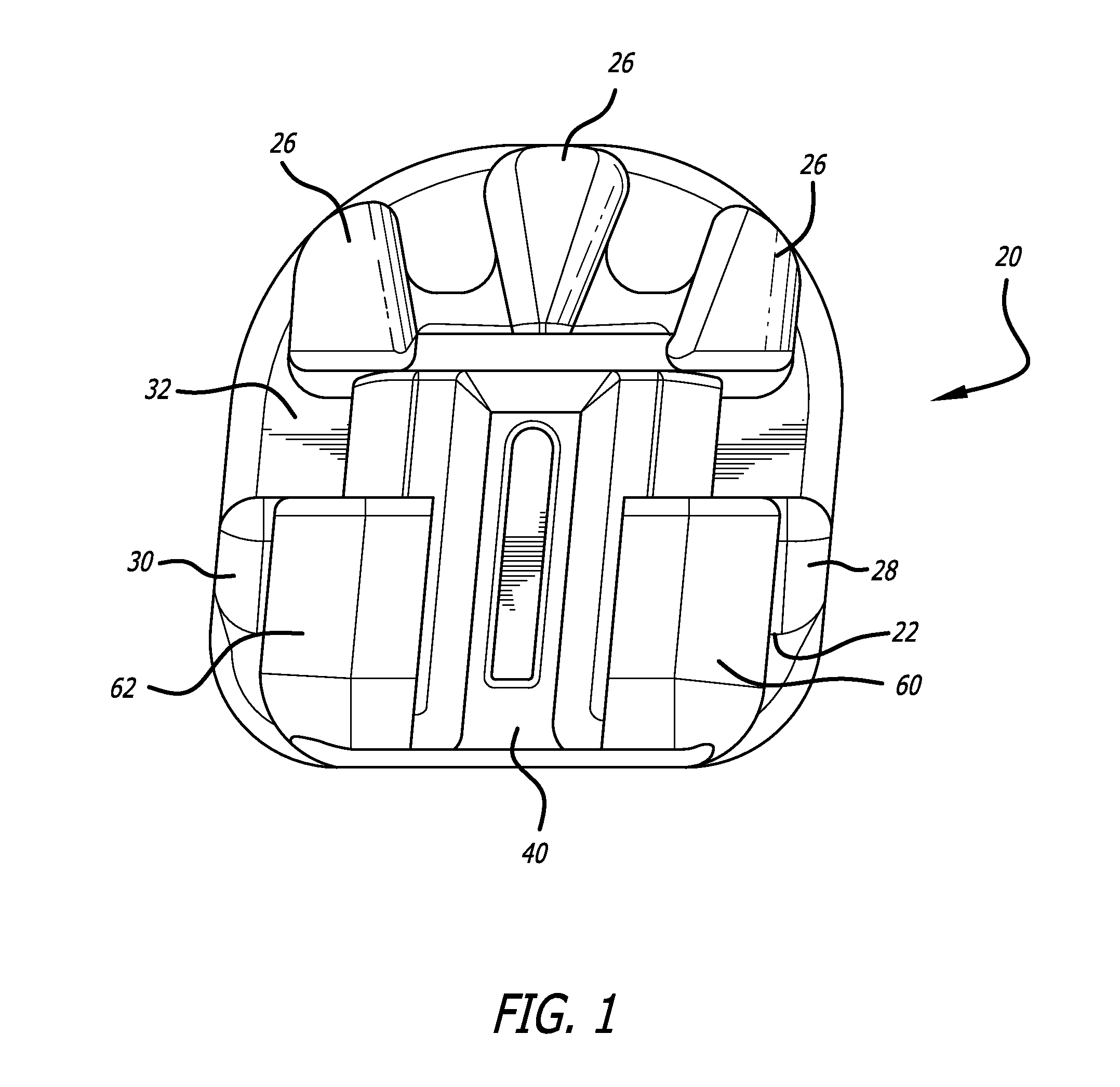
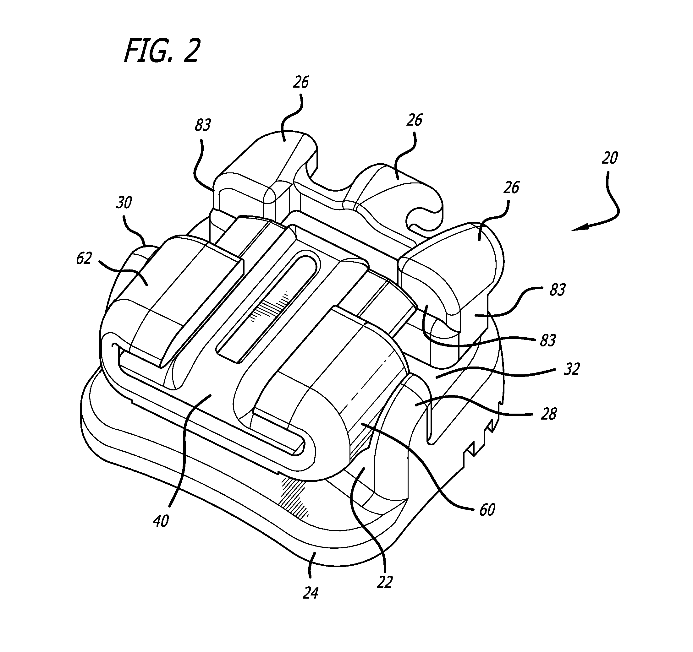
[0052]A new bracket design includes a self-ligating gate in order to provide passive archwire correction to a patient's teeth. In keeping with the invention, as shown in FIGS. 1-8, an orthodontic bracket 20 includes a bracket body 22 and a base 24. In this embodiment, the tie wings have a tri-wing design 26 which provides for a low profile in the labial-lingual height of the bracket. One advantage to the tri-wing design 26 is to enable the placement of the elastomeric chain and or traditional ligatures over the archwire slot without contacting the archwire. Importantly, if the elastomeric parts touch the archwire, they will add frictional resistance to the bracket system and thereby impair sliding mechanics. Accordingly, the tri-wing design 26 eliminates the possibility of an elastomeric touching the archwire during the correction process. A tri-wing design 26 on a self-ligating bracket is new and permits the orthodontist to use chain elastic to properly finish treatment without com...


PUM


Abstract

An orthodontic bracket includes a unitary bracket body and base and an archwire slot for receiving an archwire. A self-ligating gate is mounted on the bracket body and slides from an open position during which an archwire can be mounted in the archwire slot, to a closed position in which the ligating gate retains the archwire in the archwire slot.

Description

CROSS-REFERENCES TO RELATED APPLICATIONS[0001]This application claims priority to and the benefit of U.S. Provisional Patent Application No. 61 / 937,317, filed Feb. 7, 2014, the entire disclosure of which is expressly incorporated by reference herein.BACKGROUND[0002]Orthodontic bracket bodies have been designed in a variety of geometries or shapes. The most common bracket used in orthodontic treatment has been a twin design, where there are at least two sets of tie wings located at each end of the archslot. These are referred to as the mesial tie wings and the distal tie wings. Ligatures typically pass from the occlusal tie-wings, up and over the archwire / archslot, extending to the gingival tie-wings where they are twisted, cut and tucked under the occlusal tie wings. In this manner ligatures hold the archwire down into the archwire slot. The tie-wings also support other structures such as hooks for elastics and the tie-wings themselves can serve as a sort of macro hook, accepting th...

Claims


Application Information

Patent Timeline
Patent Type & Authority Applications(United States)
IPC IPC(8): A61C7/28A61C7/30
CPCA61C7/303A61C7/287A61C7/023A61C7/16
Inventor SABILLA, JEFFERSONCOSTELLO, AARONRUIZ-VELA, ALBERT
Owner LANCER ORTHODONTICS
Why Eureka
Try Eureka