Bar-type lighting apparatus

Active Publication Date: 2015-08-13
LINNO
View PDF6 Cites 42 Cited by
  • Summary
  • Abstract
  • Description
  • Claims
  • Application Information

AI Technical Summary

Benefits of technology

[0040]According to exemplary embodiments of the present invention, a linear lighting device in which an installation rail and a lighting module may be simply coupled to and separated from each other and at the same time, a structural connection and an electrical connection thereof may be stably formed may be provided.
[0041]Also, a linear lighting device allowing for a significant reduction in the discomforts of electrical wirings or constructions and the risk of an electric shock by connecting a housing and an external ground line to each other, as well as by connecting a power supply terminal and an external power line to each other through simply coupling an end cap portion to an end portion of the housing may be provided.
[0042]Also, a linear lighting device capable of preventing an operator from getting shocked during an operation by keeping a power supply terminal disposed within a housing from being exposed to an opening may be provided.
[0043]Also, a linear lighting device capable of significantly reducing the ri

Problems solved by technology

Since fluorescent lamps used as general lighting lamps have disadvantages such as low levels of illumination and energy efficiency, lighting modules using light emitting diodes (hereinafter, referred to as “LED”) have been recently, frequently used as lighting lamps having a relatively high level of illumination while requiring a relatively low level of power consumption as compared to the fluorescent lamps.
Thus, it is inevitable that the LED lighting modules still have the inconvenience of an existing coupling structure of a fluorescent lamp and sockets, in which a lighting module is coupled to or separated from the lamp device by a method of rotating the lighting module in a state of inserting terminals provided on both ends of the lighting module into the sockets of the lamp device, during attachment and detachment processes.
In addition, in the case of configuring linear illumination using the LED lighting module, a difference in levels of illuminance between a disposition region of the lighting module and a disposition region of the socket may occur, whereby continuous linear illumination may not be provided.
Thus, in order to separate a single LED lighting module in a state in which a plurality of LED lighting modules are disposed in a row, it is problematic in that all of lighting modules ranging from an outermost LED lighting module to a corresponding LED lighting module need to be separa

Method used


Image

  • Bar-type lighting apparatus
  • Bar-type lighting apparatus
  • Bar-type lighting apparatus

Examples


Example

[0064]Prior to the description, in several embodiments, components having the same configurations will be described using the same reference numerals representatively in a first exemplary embodiment, and other components different from those of the first exemplary embodiment will be described in other exemplary embodiments.

[0065]Hereinafter, a linear lighting device according to the first exemplary embodiment of the present invention will be described in detail with reference to the attached drawings.

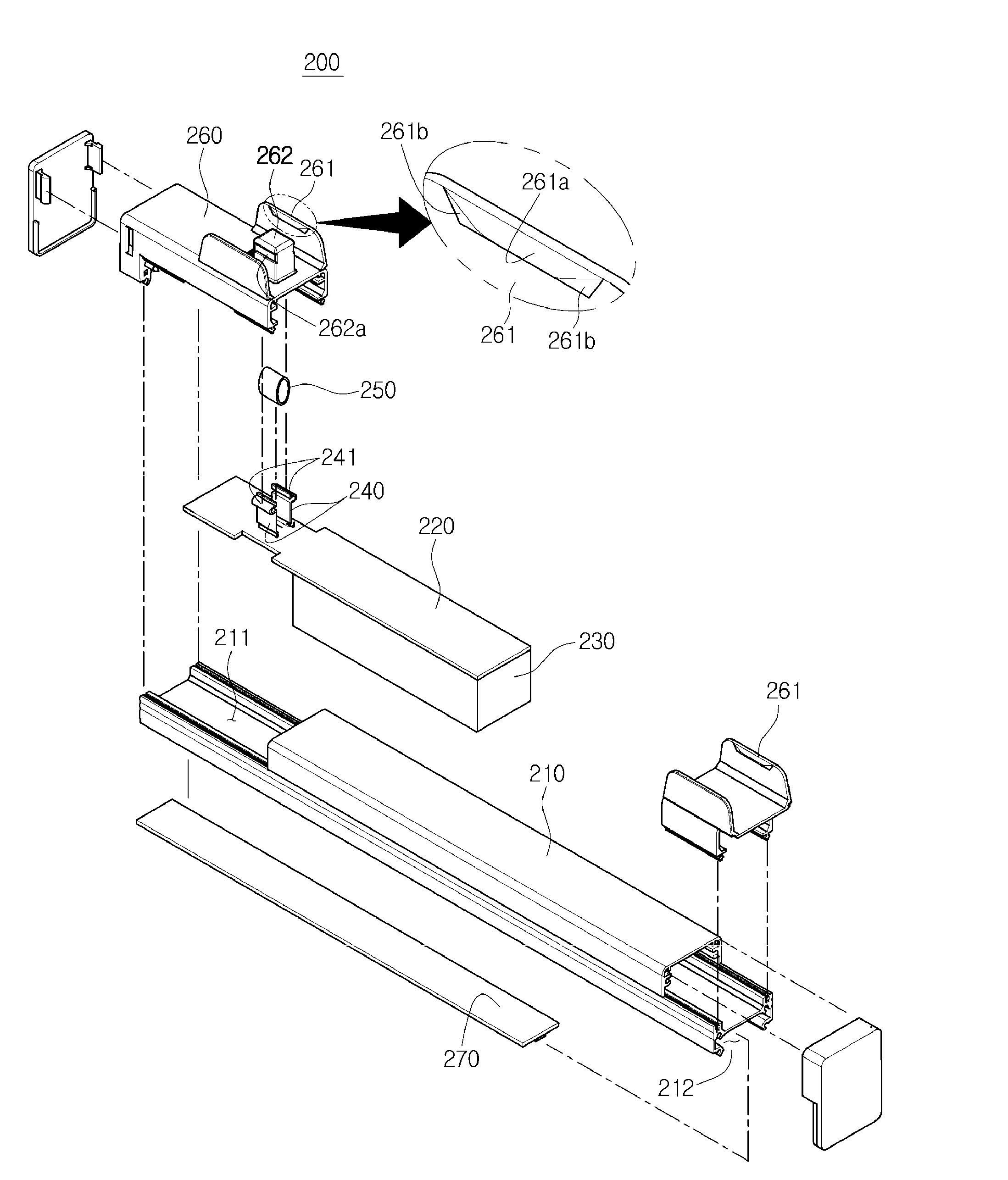
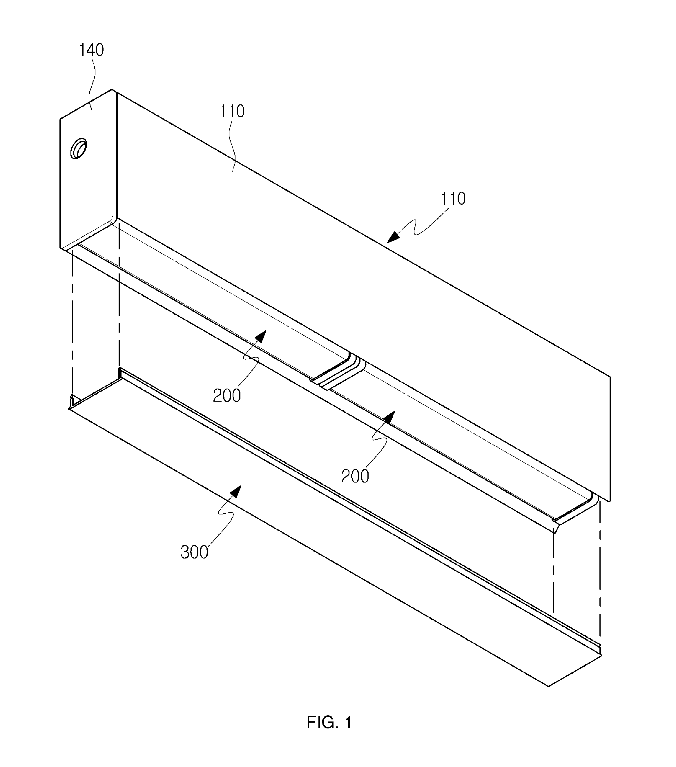
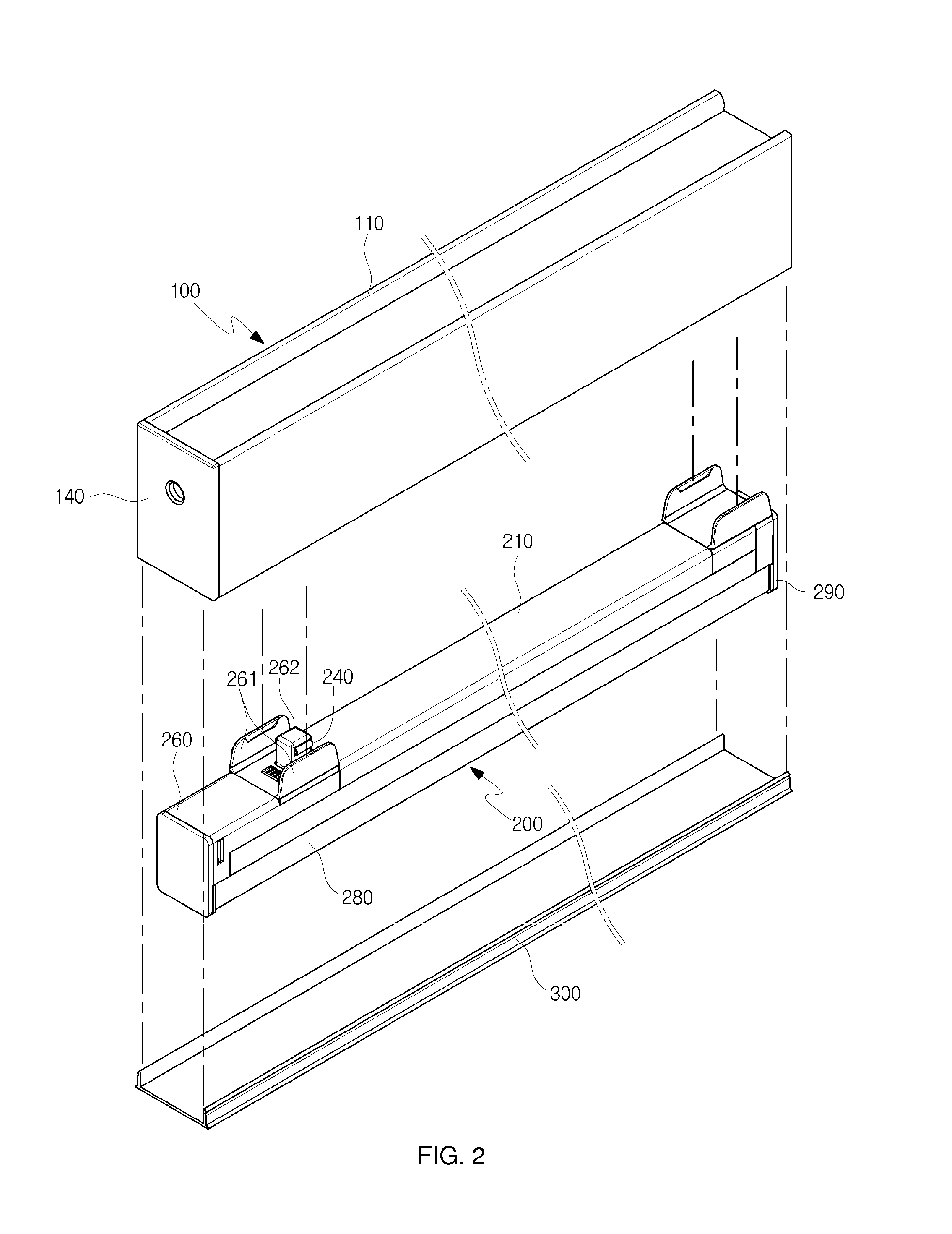
[0066]FIG. 1 is a perspective view of a linear lighting device according to a first exemplary embodiment of the present invention. FIG. 2 is an exploded perspective view of the linear lighting device according to the first exemplary embodiment of the present invention. FIG. 3 is an exploded perspective view of an installation rail of the linear lighting device according to the first exemplary embodiment of the present invention. FIG. 4 is an exploded perspective view of a lighting modul...


PUM


Abstract

A linear lighting device may include: an installation rail including a housing and a power supply terminal, the housing being fixed to an installation object surface and having an accommodating space formed therein, the accommodating space having an open side in one surface thereof, the power supply terminal being disposed in the accommodating space of the housing in a length direction thereof; at least one linear lighting module including a power connection terminal and a light emitting device, the power connection terminal being electrically connected to the power supply terminal, the light emitting device being electrically connected to the power connection terminal, the linear lighting module being detachably coupled to the accommodating space of the housing; and a light transmissive cover detachably coupled to the housing so as to close the open side of the accommodating space of the housing.

Description

TECHNICAL FIELD[0001]The present invention relates to a linear lighting device and more particularly, to a linear lighting device capable of being simply constructed by simply connecting a plurality of housings to each other in configuring an installation rail for installing a lighting module, as well as by simultaneously, electrically connecting the housings to each other in a structural connection operation.BACKGROUND ART[0002]Since fluorescent lamps used as general lighting lamps have disadvantages such as low levels of illumination and energy efficiency, lighting modules using light emitting diodes (hereinafter, referred to as “LED”) have been recently, frequently used as lighting lamps having a relatively high level of illumination while requiring a relatively low level of power consumption as compared to the fluorescent lamps.[0003]However, the majority of such LED lighting modules may be configured to replace existing fluorescent lamps to be used in a lamp device for existing...

Claims


Application Information

Patent Timeline
IPC IPC(8): F21K99/00F21V23/06
CPCF21V23/06F21K9/175F21S2/00F21V21/34F21Y2103/10F21Y2115/10F21Y2101/00F21S8/06F21S8/02F21V21/005F21V17/00
Inventor PARK, HYUN YONG
Owner LINNO
Why Eureka
Try Eureka