Induction heated roll apparatus and induction coil temperature detecting mechanism

a technology of induction heating and temperature detection mechanism, which is applied in the direction of calenders, textiles and papermaking, paper-making, etc., can solve the problems of deteriorating detection accuracy, difficult to detect accurate temperature, and often deteriorating temperature sensors

Inactive Publication Date: 2015-08-13
TOKUDEN CO LTD
View PDF2 Cites 7 Cited by
  • Summary
  • Abstract
  • Description
  • Claims
  • Application Information

AI Technical Summary

Benefits of technology

[0017]According to the present invention configured as described, the temperature of the induction coil can be detected without providing a temperature sensor inside the roll main body.

Problems solved by technology

However, in order to electrically insulate the temperature sensor and the induction coil from each other, an insulator should be made to intervene between the temperature sensor and the induction coil, and therefore there occurs a problem in that the temperature sensor is thermally insulated by the insulator and consequently deteriorates the detection accuracy.
Further, the detection accuracy also varies depending on a contact state between the temperature sensor and the induction coil, making it difficult to detect an accurate temperature.
In addition, the temperature sensor often deteriorates due to temperature and disconnects due to mechanical external force, and replacing the temperature sensor involves difficulties, such as the disassembly of the induction heated roll apparatus.

Method used


Image

  • Induction heated roll apparatus and induction coil temperature detecting mechanism
  • Induction heated roll apparatus and induction coil temperature detecting mechanism
  • Induction heated roll apparatus and induction coil temperature detecting mechanism

Examples


Embodiment Construction

[0020]In the following, one embodiment of an induction heated roll apparatus according to the present invention is described with reference to the drawings.

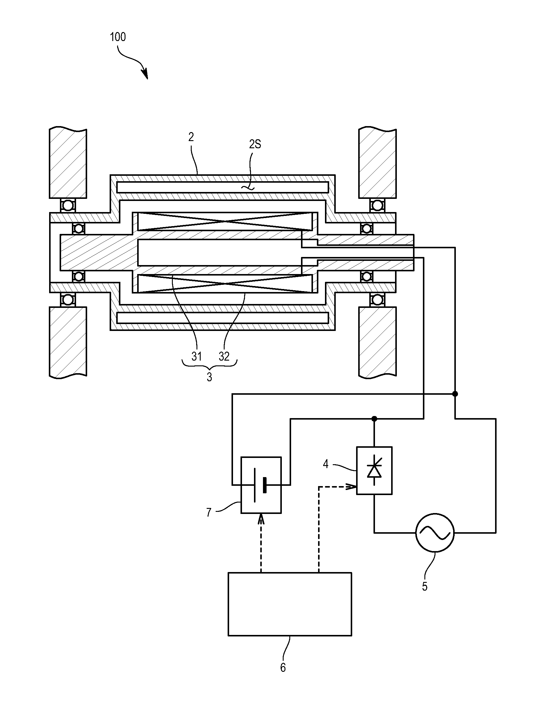
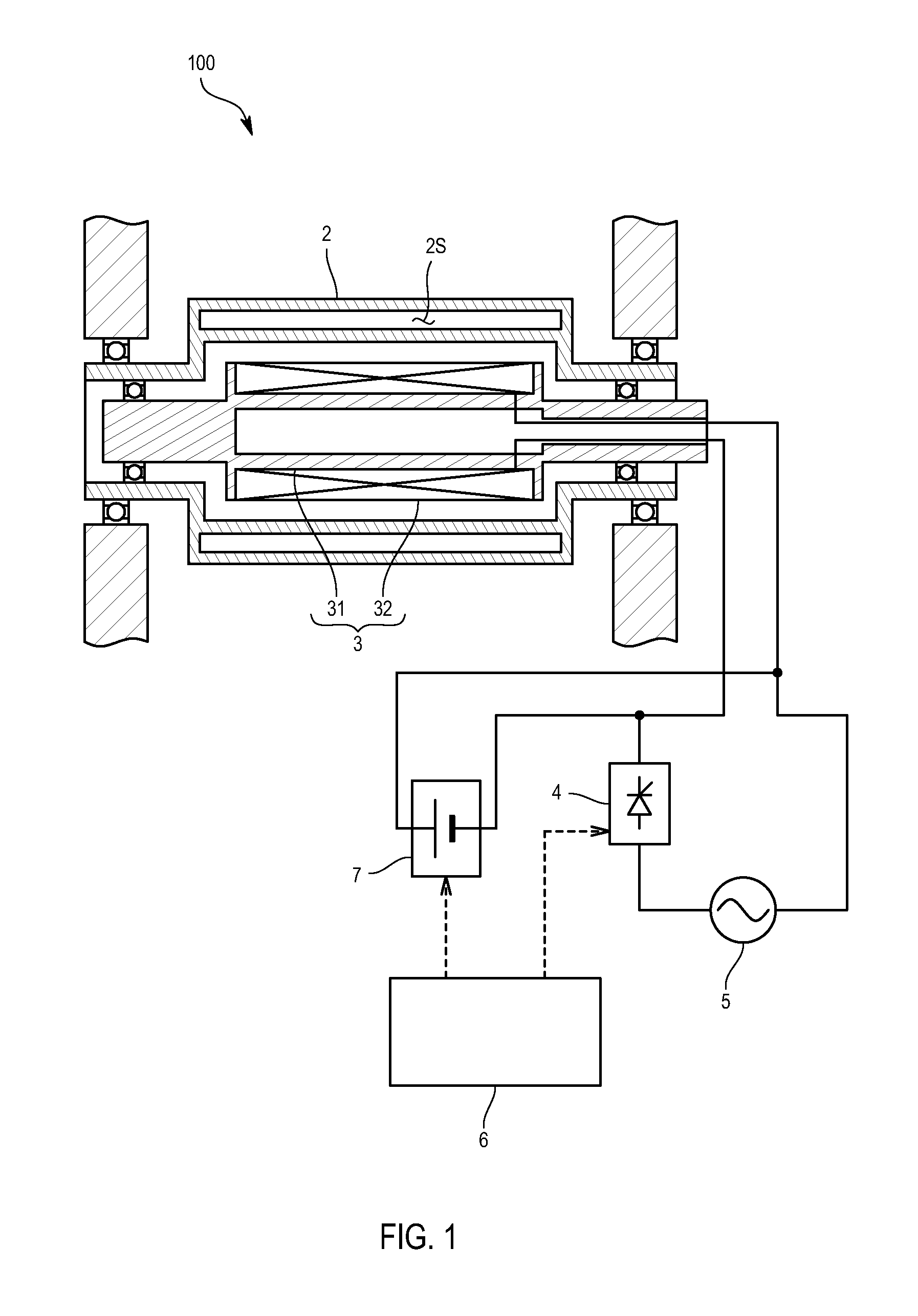
[0021]As illustrated in FIG. 1, an induction heated roll apparatus 100 according to the present embodiment includes: a roll main body 2 that is rotatably supported; a magnetic flux generating mechanism 3 that is provided inside the roll main body 2 and includes an iron core 31 and an induction coil 32 wound around the iron core 31; and a power supply circuit 5 that is connected to the induction coil 32 and provided with a control circuit part 4 adapted to control AC current or AC voltage.

[0022]Inside the lateral circumferential wall of the roll main body 2, multiple jacket chambers 2S in which a gas-liquid two-phase heating medium is included are formed at regular intervals in a circumferential direction. Also, the control circuit part 4 in the present embodiment is one that has a semiconductor element adapted to control the cond...


PUM


Abstract

The present invention intends to detect the temperature of an induction coil without providing a temperature sensor inside a roll main body, and includes: a DC voltage application part that controls a DC power supply to intermittently apply DC voltage to the induction coil; a resistance value calculation part that calculates a resistance value of the induction coil from the DC voltage applied by the DC voltage application part and DC current flowing through the induction coil; a relational data storage part that stores relational data indicating a resistance value versus temperature relationship between the resistance value of the induction coil and the temperature of the induction coil; and a coil temperature calculation part that calculates the temperature of the induction coil from the resistance value obtained by the resistance value calculation part and the resistance value versus temperature relationship indicated by the relational data.

Description

TECHNICAL FIELD[0001]The present invention relates to an induction heated roll apparatus, and a temperature detecting mechanism adapted to detect the temperature of an induction coil of the induction heated roll apparatus.BACKGROUND ART[0002]As disclosed in Patent Literature 1, an induction heated roll apparatus includes: a roll main body that is rotatably supported; and a magnetic flux generating mechanism that is provided inside the roll main body and includes an iron core and an induction coil wound around the iron core, and the induction coil is typically placed inside the roll main body. The induction coil is often heated to a high temperature by self-heating due to current application, and heat is applied to the roll main body that is inductively heated.[0003]For this reason, in order to prevent the induction coil from being heated to a high temperature exceeding an allowable heat resistant temperature and thereby becoming burned out, a temperature sensor is generally embedded...

Claims


Application Information

Patent Timeline
Patent Type & Authority Applications(United States)
IPC IPC(8): H05B6/36H05B1/02
CPCH05B1/02H05B6/36D21G1/028H05B6/06H05B6/145
Inventor TONOMURA, TORUFUJIMOTO, YASUHIROKIMURA, MASAYOSHI
Owner TOKUDEN CO LTD
Why Eureka
Try Eureka