Nitriding method and device

a nitriding treatment and nitriding treatment technology, applied in adaptive control, process and machine control, instruments, etc., can solve the problems of unstable glow discharge, inability to apply uniform nitriding treatment, and part of the workpiece surface, so as to achieve satisfactory nitriding treatment, high accuracy, and high accuracy.

Inactive Publication Date: 2006-06-15
HONDA MOTOR CO LTD
View PDF2 Cites 3 Cited by
  • Summary
  • Abstract
  • Description
  • Claims
  • Application Information

AI Technical Summary

Benefits of technology

[0007] A general object of the present invention is to provide a nitriding treatment method and a nitriding treatment apparatus in which a workpiece is heated quickly and uniformly up to a temperature at which a stable nitriding treatment can be performed, making it possible to apply the nitriding treatment in a state in which the workpiece temperature dispersion is scarcely caused.
[0016] Further, in the present invention, in order to detect the workpiece temperature highly accurately without using any contact type thermometer, a dummy workpiece is arranged in the heat treatment furnace. The contact temperature and the radiation temperature of the dummy workpiece are detected, and the radiation temperature of the workpiece is detected. The radiation temperature of the workpiece is corrected on the basis of the difference in temperature between the contact temperature and the radiation temperature of the dummy workpiece to estimate the temperature of the workpiece itself. When the heating, which is effected by the glow discharge and the heating element, is controlled on the basis of the workpiece temperature estimated as described above, then the workpiece temperature can be managed highly accurately, and it is possible to perform the extremely satisfactory nitriding treatment.

Problems solved by technology

In the case of such a treatment, when the workpiece is cold, the glow discharge becomes unstable.
Depending on certain situations, any inconvenience arises such that the arc discharge is caused, and a part of the workpiece surface is melted, and / or it is impossible to apply any uniform nitriding treatment.
In particular, when the temperature distribution of the workpiece is nonuniform, it is impossible to obtain satisfactory products, because the degree of advance of nitriding differs depending on the positions of the product.

Method used


Image

  • Nitriding method and device
  • Nitriding method and device
  • Nitriding method and device

Examples


Embodiment Construction

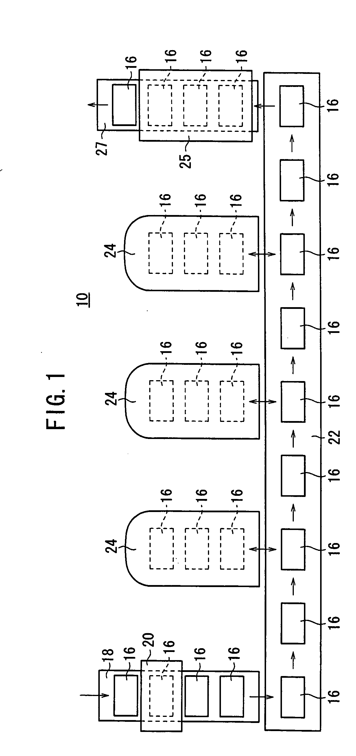
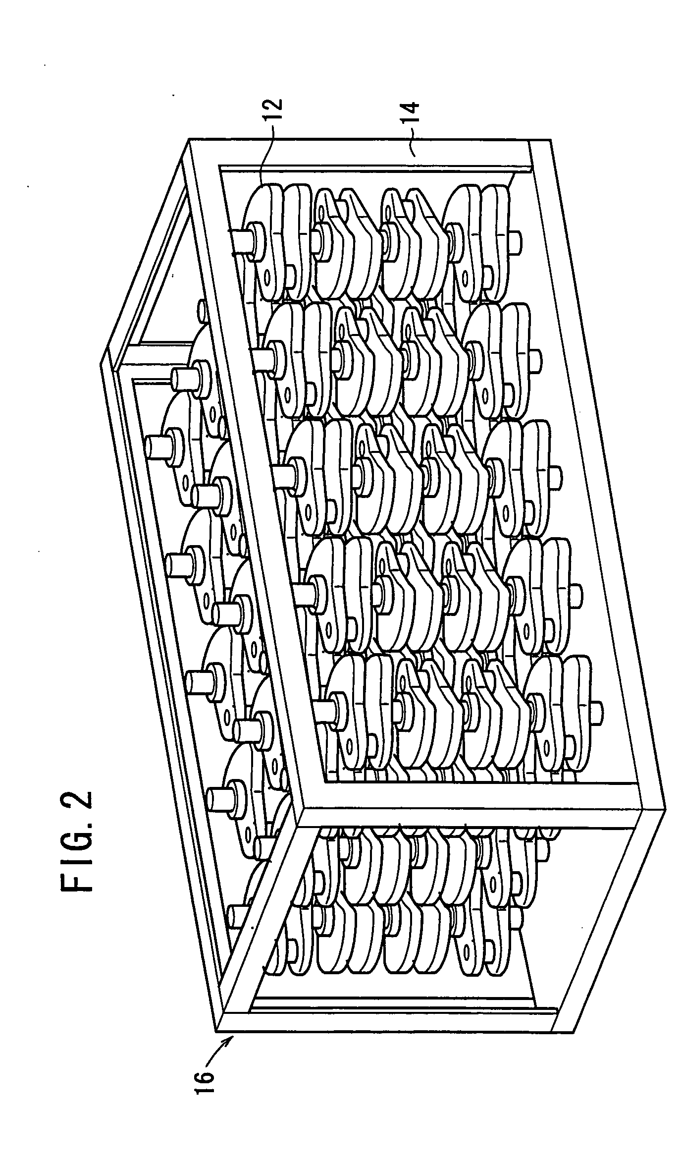
[0022]FIG. 1 shows a schematic arrangement of a nitriding treatment system 10 including a nitriding treatment apparatus according to an embodiment of the present invention. As shown in FIG. 2, a plurality of crank shafts 12 as workpieces are supplied to the nitriding treatment system 10 in a form of a magazine 16 in which the plurality of crank shafts 12 are positioned with a jig 14.

[0023] The nitriding treatment system 10 comprises a washing machine 20 which removes, for example, dust and oil adhered to the crank shafts 12 transported by a conveyer 18, a conveyer 22 which receives the washed crank shafts 12 from the conveyer 18 to transport them to respective work stations, lateral type heat treatment furnaces 24 which are arranged at the plurality of work stations along the conveyer 22, and a cooling tank 25 which cools the crank shafts 12 transported by a conveyer 27 connected to the terminal end of the conveyer 22.

[0024]FIG. 3 illustrates an arrangement of the lateral type hea...


PUM

PropertyMeasurementUnit
frequencyaaaaaaaaaa
temperatureaaaaaaaaaa
current densityaaaaaaaaaa

Abstract

A pulse voltage having a frequency of 15 kHz is applied from a discharging power supply unit (48) to between a crankshaft (12) and an electrode plate (45) at a current density of 2.5 mA / cm2 to generate a glow discharge and an electric heater (34) is driven at a 40% output (64 kW / kg) to heat the crankshaft (12) to up to 400° C., and then heating is continued with the current density of a glow discharge set at 0.5 mA / cm2 and the output of the electric heater (34) set at 90% (144 kW / kg), thereby effecting nitriding at a desired nitriding temperature.

Description

TECHNICAL FIELD [0001] The present invention relates to a nitriding treatment method and a nitriding treatment apparatus for performing a nitriding treatment for a workpiece in a heat treatment furnace. BACKGROUND ART [0002] The nitriding treatment resides in a process in which a surface of a workpiece composed of a steel material is nitrided to form an iron nitride layer, and thus the surface of the workpiece is hardened. The nitriding treatment is widely carried out. A method for the nitriding treatment includes a plasma nitriding treatment in which the plasma heating is performed by means of the glow discharge. [0003] In the case of such a treatment, when the workpiece is cold, the glow discharge becomes unstable. Depending on certain situations, any inconvenience arises such that the arc discharge is caused, and a part of the workpiece surface is melted, and / or it is impossible to apply any uniform nitriding treatment. In particular, when the temperature distribution of the work...

Claims


Application Information

Patent Timeline
Patent Type & Authority Applications(United States)
IPC IPC(8): C23C8/36C23C8/24H05H1/46C21D1/06
CPCC23C8/36C23C14/3485C23C14/548G05B13/02
Inventor TAKEUCHI, YUTAKAKARASAWA, HITOSHIKOJIMA, HIDEO
Owner HONDA MOTOR CO LTD
Why Eureka
Try Eureka