Process for predrying a coil block containing at least one winding and solid insulation

a technology of solid insulation and predrying process, which is applied in the direction of ovens, magnetic bodies, ovens, etc., can solve the problem of requiring little maintenan

Inactive Publication Date: 2000-06-27
ABB (SCHWEIZ) AG
View PDF19 Cites 5 Cited by
  • Summary
  • Abstract
  • Description
  • Claims
  • Application Information

AI Technical Summary

Benefits of technology

At the same time, the autoclave 1 and thus the air present in the autoclave are heated. The combined heating with direct current and air causes the heat required for predrying the solid insulations of the coil blocks to be supplied at the same time both from inside and outside. This results in an especially quick and gentle drying. Water bound in the solid insulations is fed away from the heated windings outwards to the surfaces of the solid insulations, and is absorbed by the air as water vapor. By circulating the air with the help of the convection air fan, parts of the solid insulations, such as, e.g., barrier insulations located between two windings, which are not in direct contact with a winding of the coil block, are heated especially quickly and uniformly, and the water exiting the solid insulations is removed quickly from the coil blocks. Here it is especially recommended that the circulating air stream is guided in such a manner that it flows between the individual coil blocks 5, 6, 7 from the bottom to the top. By reducing the air pressure, the discharge of the water from the solid insulations is promoted.
During the entire heating phase and during the holding of the windings at the upper winding temperature, a uniformly acting compression pressure is applied to the coil blocks. This compression pressure is generated by the compression device 15, and can, according to the air pressure in the autoclave, have a pulsing effect. The compression pressure causes the coil blocks to be stabilized and adapted to the given dimensions.

Problems solved by technology

The devices accommodated inside the housing, in particular the hydraulic compression devices intended for exerting pressure on the coil blocks, therefore require little maintenance.

Method used


Image

  • Process for predrying a coil block containing at least one winding and solid insulation
  • Process for predrying a coil block containing at least one winding and solid insulation
  • Process for predrying a coil block containing at least one winding and solid insulation

Examples


Embodiment Construction

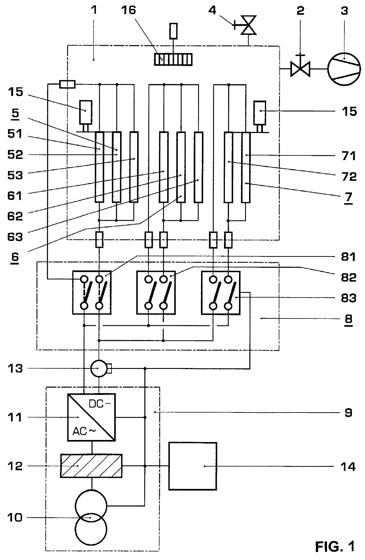
In all figures, identical reference numbers refer to parts with the same function. In the device for performing the process according to the invention as shown in FIG. 1, the number 1 refers to a vacuum-tight autoclave connected via a straight-way valve 2 to a vacuum pump 3, said autoclave being connectable via a ventilation valve 4 with circulating air. The autoclave holds three windings 51, 52, 53 or 61, 62, 63 or 71, 72 respectively, and coil blocks 5 or 6 or 7 provided with solid insulations (not shown). The windings, e.g. 51, 52, 53, of each coil block, e.g., 5, can be constructed in the same manner and are switched parallel to each other. Two power connections to the windings of each coil block are guided through feed-throughs (not referenced) from the inside of the autoclave 1 to a switching device 8 which itself is in effective connection with the output of a direct current source 9.

The direct current source 9 is equipped with a transformer 10 and a rectifier 11 acting on th...


PUM

PropertyMeasurementUnit
air pressureaaaaaaaaaa

Abstract

The process is used for predrying a coil block (5) inside a gas-tight housing (1), said coil block containing at least one winding (51) and solid insulations. The winding is hereby heated under reduced pressure with direct current or low-frequency alternating current to an upper winding temperature. Parallel to this, the solid insulations are heated with air circulating inside the housing (1). The air temperature is hereby maintained lower than the winding temperature. The combined heating with heating current and circulating air results in an especially uniform predrying, and at the same time saves time and energy. At the same time, the winding can be stabilized and dimensioned during the predrying process under the action of pressure.

Description

FIELD OF TECHNOLOGYThe invention is based on a process for predrying a coil block containing at least one winding, in which the at least one winding is heated with an electric current under reduced pressure in a gas-tight housing. Such a process is usually used for stabilizing the coil block prior to installation. into an electric machine or electric apparatus, e.g., a transformer. When simultaneously using pressure, the process can also be used to adapt the geometric dimensions of the coil block to parts of the machine or device which carry the coil block, and which support it so that it will be able to absorb short-circuit forces.STATE OF THE ARTA process of the above mentioned type is described in JP 5006833 A. In this process, a winding of a coil block is heated with a direct current under a vacuum in a drying oven. Moisture discharged from the heated coil block is removed from the inside of the drying oven by means of a vacuum device. A temperature regulator based on a thermoel...

Claims


Application Information

Patent Timeline
Patent Type & Authority Patents(United States)
IPC IPC(8): H01F27/10H01F27/14
CPCH01F27/14Y10T29/49073
Inventor GMEINER, PAUL
Owner ABB (SCHWEIZ) AG
Why Eureka
Try Eureka