Reflecting shell and temperature detecting device

a technology of temperature detection and reflecting shell, which is applied in the direction of heat measurement, optical radiation measurement, instruments, etc., can solve the problems of inconvenient use, inability to measure the temperature of more than one person, and method may harbor hygienic concerns, and achieve the effect of longer detecting distan

Active Publication Date: 2020-10-13
RADIANT INNOVATION INC
View PDF10 Cites 2 Cited by
  • Summary
  • Abstract
  • Description
  • Claims
  • Application Information

AI Technical Summary

Benefits of technology

[0007]One of the beneficial advantages of the present disclosure is that the reflecting shell and the temperature detecting device have technical features of “one end of the hollow joint unit has a stationary part, and the stationary part is detachably connected with the detecting part of the detecting device”, “one end of the hollow guide unit is connected with the other end of the hollow joint unit, and an inner wall of the hollow guide unit has a first reflective surface and a second reflective surface which correspond to each other”, “one end of the hollow receiving unit is connected with the other end of the hollow guide unit”, and “heat radiation from at least one heat source enters the hollow guide unit through the end of the hollow receiving unit which is connected with the hollow guide unit, and the heat radiation transmits to the detecting part by the reflection of the first reflective surface and the second reflective surface”, so that the detecting device has the function of taking forehead temperature. Compared with the conventional non-contact thermometer, the detecting device of the present disclosure has the focusing function and a longer detecting distance. In addition, the temperature detecting device of the present disclosure can both detect ear temperature and forehead temperature.

Problems solved by technology

Since the traditional thermometers are usually used to measure the temperature of mouth, underarm, and anus, they are inconvenient to use and cannot measure the temperature of more than one person at a time.
The method of measuring ear temperature by the ear thermometer is inserting the head of the ear thermometer into a subject's ear; however, this method may harbor hygienic concerns.
The forehead thermometers are non-contact measuring devices and are more hygienic, but due to their sensitivity to surroundings and measuring distance, the measured results are often inaccurate.
Moreover, the ear thermometer and the forehead thermometer cannot both be incorporated on one device, so that it is hard to improve the convenience and scope of application thereof, and further results in the need for a user to prepare both at the same time, which is inconvenient and costly.

Method used


Image

  • Reflecting shell and temperature detecting device
  • Reflecting shell and temperature detecting device
  • Reflecting shell and temperature detecting device

Examples


first embodiment

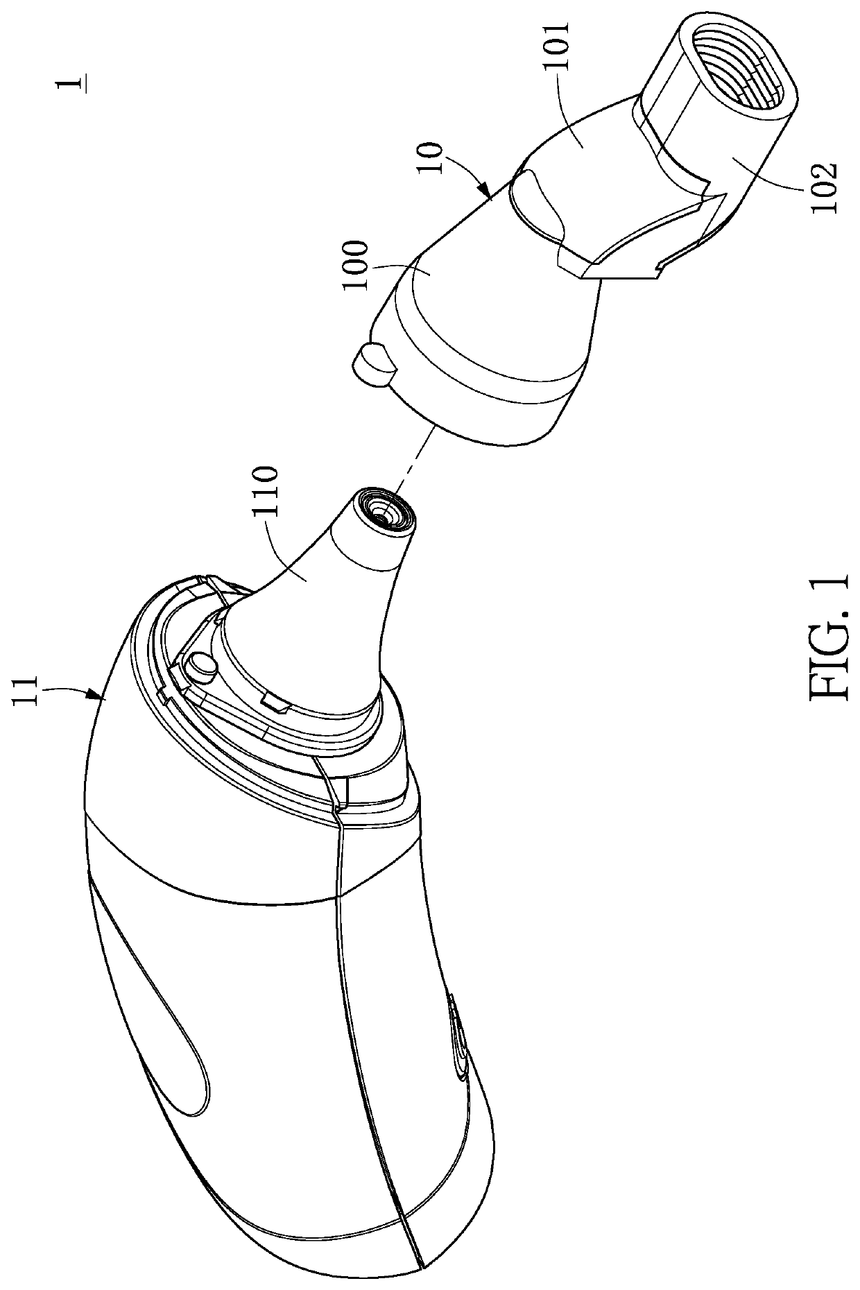
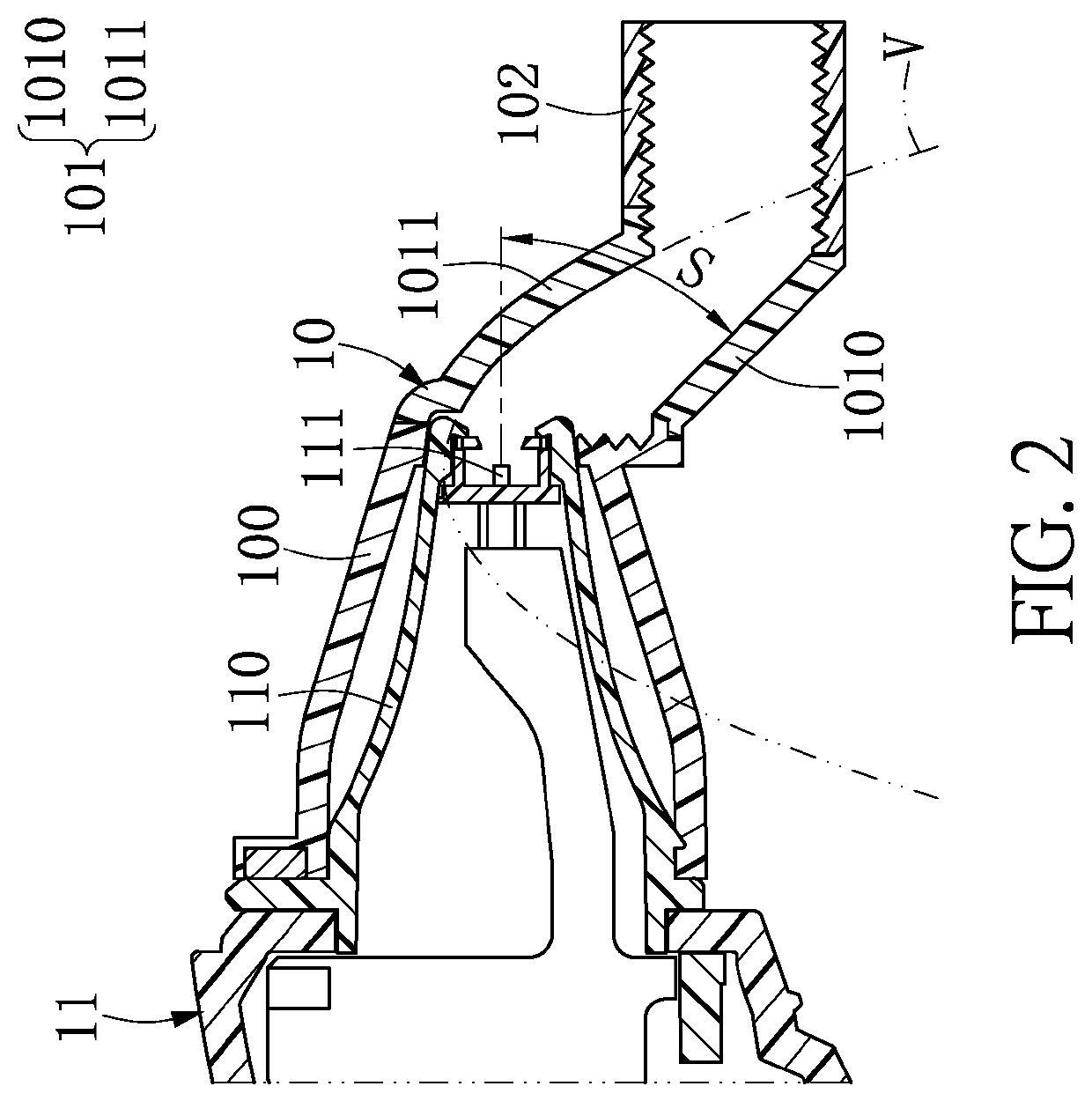
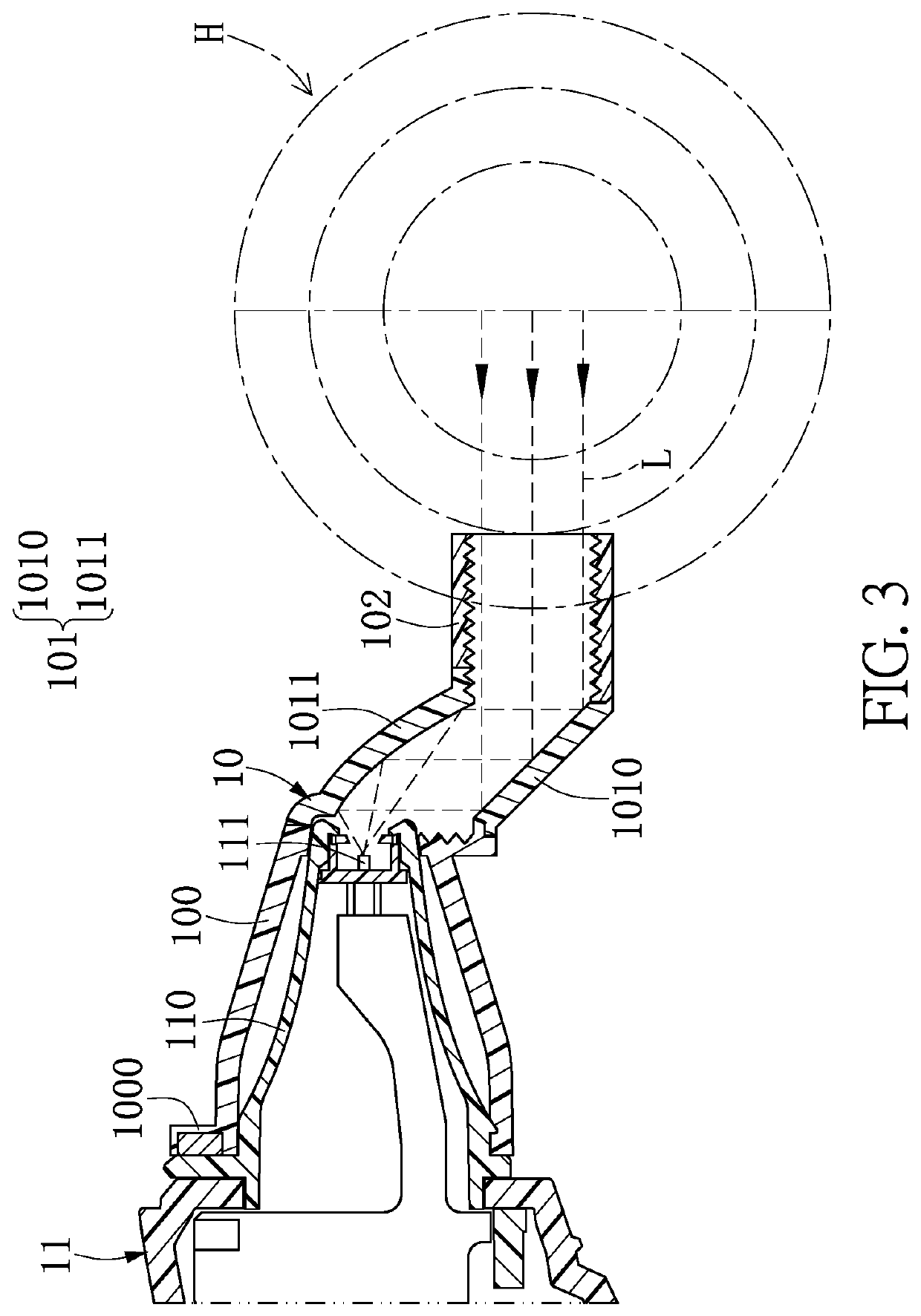
[0025]Referring to FIG. 1 to FIG. 8, FIG. 1 is a stereoscopic view of a reflecting shell according to a first embodiment of the present disclosure; FIG. 2 is a cross-sectional view of the reflecting shell according to the first embodiment of the present disclosure; FIG. 3 to FIG. 5 are first to third schematic views, respectively, according to the first embodiment of the present disclosure, illustrating the reflection paths that reflecting shell reflects heat radiation received from heat sources at different distance; FIG. 6 to FIG. 8 are first to third schematic views, respectively, according to the first embodiment of the present disclosure, illustrating the reflecting shell receives heat radiation from heat sources having a large angle at different distances. According to the foregoing figures, the first embodiment of the present disclosure provides a reflecting shell 10 including a hollow joint unit 100, a hollow guide unit 101, and a hollow receiving unit 102. One end of the ho...

second embodiment

[0034]Reference is made to FIG. 9, which is a cross-sectional view of the reflecting shell according to a second embodiment of the present disclosure, and with further reference made to FIGS. 1 to 8. By the figures mentioned above, the second embodiment of the present disclosure provides another configuration of the reflecting shell 10 which is similar to that in the first embodiment, but the difference being that the inner wall of the hollow receiving unit 102 of the reflecting shell 10 of the second embodiment has a matting part 1020.

[0035]For example, the inner wall of the hollow receiving unit 102 may be formed with a matting part 1020, and the matting part 1020 can be a rough jagged structure or a coating with low emissivity by spraying, but is not limited thereto. The hollow joint unit 100 can further have a radiation removing part 1001 at the position being connected with the hollow receiving unit 102. The radiation removing part 1001 can be a rough jagged structure, but is n...

third embodiment

[0038]Reference is next made to FIG. 10 and FIG. 11, with further reference FIGS. 1 to 9. FIG. 10 is a stereoscopic view of a temperature detecting device according to a third embodiment of the present disclosure, and FIG. 11 is a cross-sectional perspective view of the temperature detecting device according to the third embodiment of the present disclosure. The operation of the measuring device 1 of the third embodiment is similar with that of the reflecting shell 10 in the above embodiments, and is not described in detail therein. By the figures mentioned above, the third embodiment of the present disclosure provides a temperature detecting device 1 including the detecting device 11 and the reflecting shell 10. The detecting device 11 includes a detecting part 110 for receiving infrared light. The reflecting shell 10 includes the hollow joint unit 100, the hollow guide unit 101 and the hollow receiving unit 102. One end of the hollow joint unit 100 has the stationary part 1000, an...


PUM

PropertyMeasurementUnit
angleaaaaaaaaaa
angleaaaaaaaaaa
distancesaaaaaaaaaa

Abstract

A reflecting shell includes a hollow joint unit, a hollow guide unit and a hollow receiving unit. The hollow joint unit has a stationary part at one end, and the stationary part is detachably connected to a detecting part of a measuring device. One end of the hollow guide unit is connected to the other end of the hollow joint unit, and an internal wall of the hollow guide unit has a first reflective surface and a second reflective surface, in which the first reflective surface and the second reflective surface correspond to each other. One end of the hollow receiving unit is connected to the other end of the hollow guide unit. Heat radiation from a heat source enters the hollow guide unit, and the heat radiation is transmitted to the detecting part by the reflection of the first reflective surface and the second reflective surface.

Description

FIELD OF THE DISCLOSURE[0001]The present disclosure relates to a reflecting shell and a temperature detecting device, and more particularly to a reflecting shell which allows a measuring device to measure a forehead temperature, and a temperature detecting device which can measure both ear temperature and forehead temperature.BACKGROUND OF THE DISCLOSURE[0002]In recent years, due to changes in temperature and environment, a variety of viruses and germs have bred and thrived, e.g., enterovirus, influenza. Therefore, people's awareness of self-health management has also increased. When feeling discomfort, people would take their own temperature to determine whether or not they are coming down with a fever, and if yes, they would seek medical advice as soon as possible which can reduce the spread of infectious diseases.[0003]The conventional devices for taking body temperature are divided into traditional thermometers and modern thermometers, e.g., ear thermometers and forehead thermom...

Claims


Application Information

Patent Timeline
Patent Type & Authority Patents(United States)
IPC IPC(8): G01J5/00G01J5/04G01J5/02G01K13/00
CPCG01J5/025G01J5/0025G01J5/021G01J5/049G01K13/004G01J5/0205G01J5/0806G01J5/0808G01J5/07G01K13/223
Inventor LIN, TSENG-LUNGKU, CHIN-HUI
Owner RADIANT INNOVATION INC
Why Eureka
Try Eureka