Detection device and detection method for cable status of transponder

A detection device and transponder technology, applied in the field of circuits, can solve the problems of insufficient long-distance open/short detection capability, inability to distinguish between separate/short-circuit states, etc.

Inactive Publication Date: 2012-07-11
BEIJING HOLLYSYS
View PDF5 Cites 13 Cited by
  • Summary
  • Abstract
  • Description
  • Claims
  • Application Information

AI Technical Summary

Problems solved by technology

[0009] Traditional detection methods have defects such as insufficient long-distance open/sh

Method used


Image

  • Detection device and detection method for cable status of transponder
  • Detection device and detection method for cable status of transponder
  • Detection device and detection method for cable status of transponder

Examples


Embodiment 1

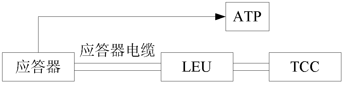
[0046] Embodiment 1, a detection device for the state of the transponder cable, connected to the output end of the trackside electronic unit connected to the transponder, including:

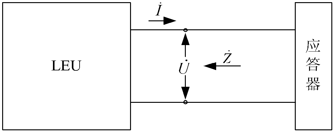
[0047] The collection module is used to collect the voltage and current on the output terminal of the connected trackside electronic unit;

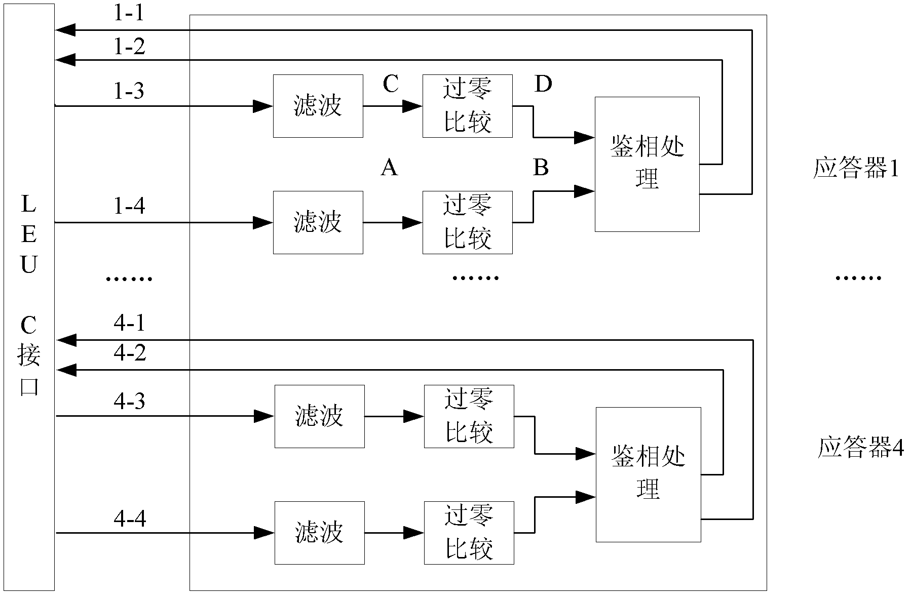
[0048] The phase detection module is used to compare the phases of the collected voltage and current. If the voltage phase is ahead of the current phase, it is judged that the transponder cable is short-circuited; if the current phase is ahead of the voltage phase, it is judged whether the phase difference between the current and the voltage is Less than or equal to the preset threshold, if it is judged that the transponder cable is open, if not, it is judged that the transponder cable is normal.

[0049] In this embodiment, the preset threshold can be selected according to theoretical results; the impedance phase difference (that is, the difference between ...

Embodiment 2

[0083] Embodiment 2. A method for detecting the state of a transponder cable, comprising:

[0084] Collect the voltage and current on the output terminal of the trackside electronic unit connected to the transponder;

[0085] Compare the phases of the collected voltage and current, if the voltage phase is ahead of the current phase, it is judged that the transponder cable is short-circuited;

[0086] If the current phase is ahead of the voltage phase, it is judged whether the phase difference between the current and voltage is less than or equal to the preset threshold, if yes, it is judged that the transponder cable is open, if not, it is judged that the transponder cable is normal.

[0087] In this embodiment, the step of collecting the voltage and current on the output end of the trackside electronic unit connected to the transponder may specifically include:

[0088] Collect the voltage and current on the output terminal of the connected trackside electronic unit;

[008...


PUM


Abstract

The invention discloses a detection device and a detection method for a cable status of a transponder. The detection device is connected onto the output end of the transponder connected with a trackside electronic unit. The detection device comprises an acquisition module and a phase discrimination module, wherein the acquisition module is used for acquiring the voltage and the current of the output end of the trackside electronic unit; the phase discrimination module is used for comparing the phase of the acquired voltage with the phase of the acquired current; if the phase of the voltage is in advance of the phase of the current, a cable of the transponder is judged to be short-circuited; if the phase of the current is in advance of the phase of the voltage, whether the phase difference between the current and the voltage is less than or equal to a preset threshold value or not is judged; if the phase difference between the current and the voltage is less than or equal to the preset threshold value, the cable of the transponder is judged to be open-circuited; and if the phase difference between the current and the voltage is not less than or equal to the preset threshold value, the cable of the transponder is judged to be normal. According to the detection device for the cable status of the transponder, the cable status can be detected under the condition of long distance, and the open-circuited status, the short-circuited status and the normal status are correctly distinguished.

Description

technical field [0001] The invention relates to the field of circuits, in particular to a detection device and a detection method for the state of a transponder cable. Background technique [0002] With the continuous improvement of railway speed and density, active transponders play a vital role in improving train transportation efficiency and enhancing system security. [0003] The active transponder provides information such as route and temporary speed limit order to the train in real time to control the train operation. figure 1 Shown is the configuration diagram of TCC (Train Control Center, train control center), LEU (Lineside Electronic Unit, trackside electronic unit) and transponder. TCC transmits the message to LEU in real time; LEU adopts a safe and transparent transmission protocol to complete the transmission of TCC message to the transponder; ATP (Automatic Train Protection, automatic train protection device) controls the train according to the received trans...

Claims


Application Information

Patent Timeline
IPC IPC(8): G01R31/02
Inventor 张平孙宁先王连福何春明李剑李智
Owner BEIJING HOLLYSYS
Why Eureka
Try Eureka