

Steering Apparatus
- Summary
- Abstract
- Description
- Claims
- Application Information
AI Technical Summary
Benefits of technology
Problems solved by technology
Method used
Image

Examples
first embodiment
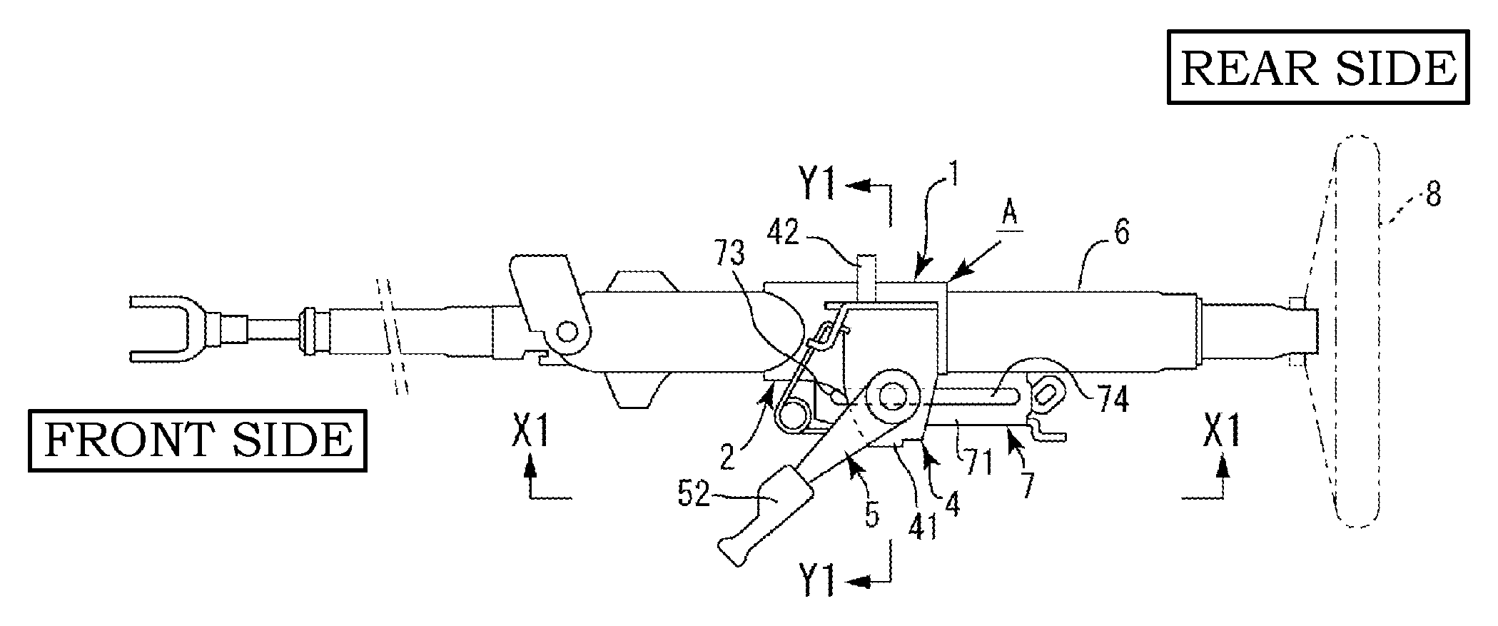
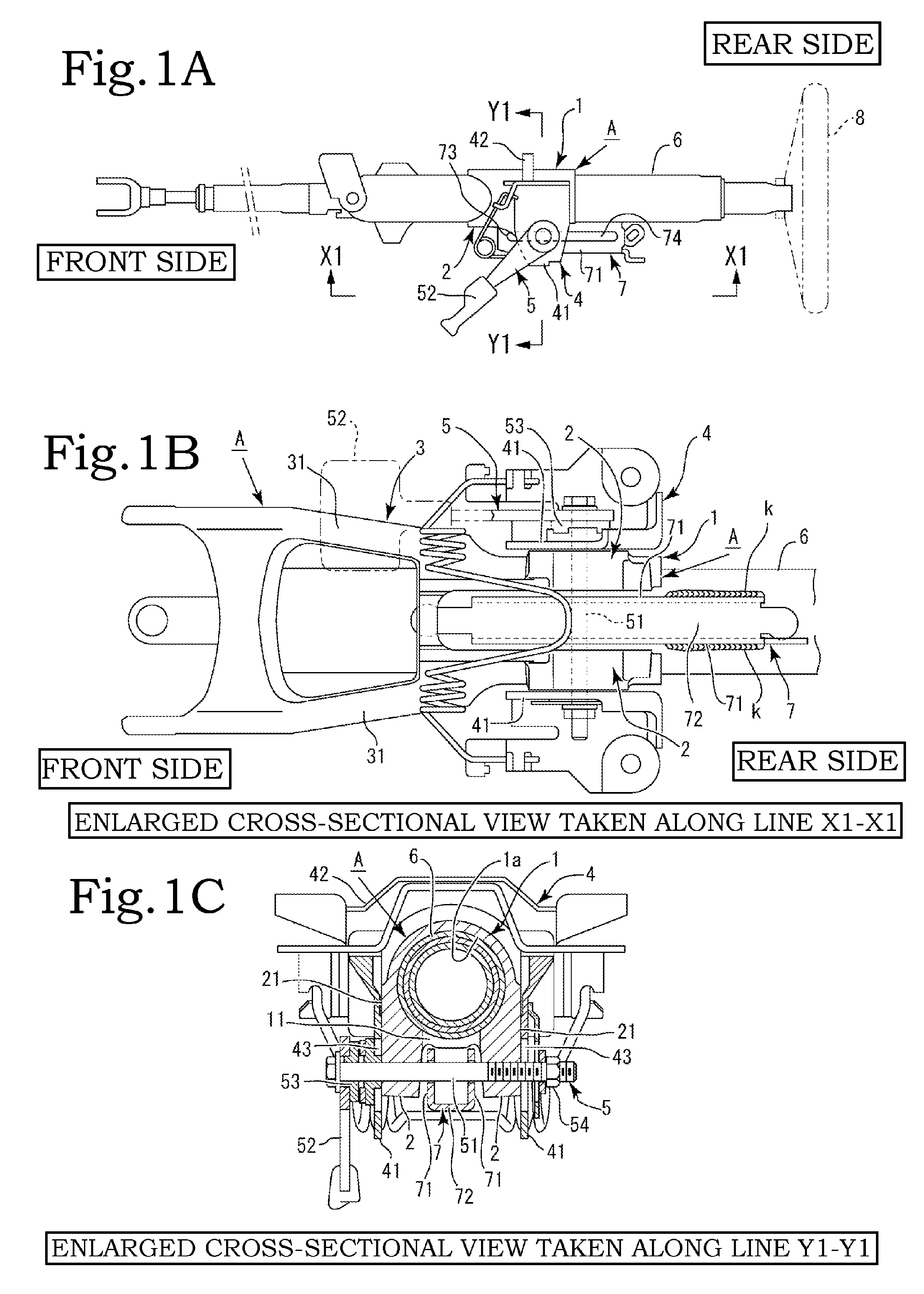
[0031]Embodiments of the present invention will be described based on the drawings. The present invention has a plurality of embodiments, and a first embodiment will be described first. A “front side” and a “rear side” are present herein as terms representing directions according to the present invention. The front side and the rear side are based on a front-rear direction of a car in which a steering apparatus according to the present invention is installed. Specifically, with respect to components of the steering apparatus, a front wheel side of the car corresponds to the front side, and a steering wheel 8 side corresponds to the rear side.
[0032]As depicted in FIG. 1, main components of the present invention include an outer column A, a fixing bracket 4, a clamper 5, a column pipe 6, and a stopper bracket 7. The outer column A includes an embracing main body portion 1 and a clamping portion 2. The embracing main body portion 1 is shaped generally like an internally hollow cylinder...
fourth embodiment
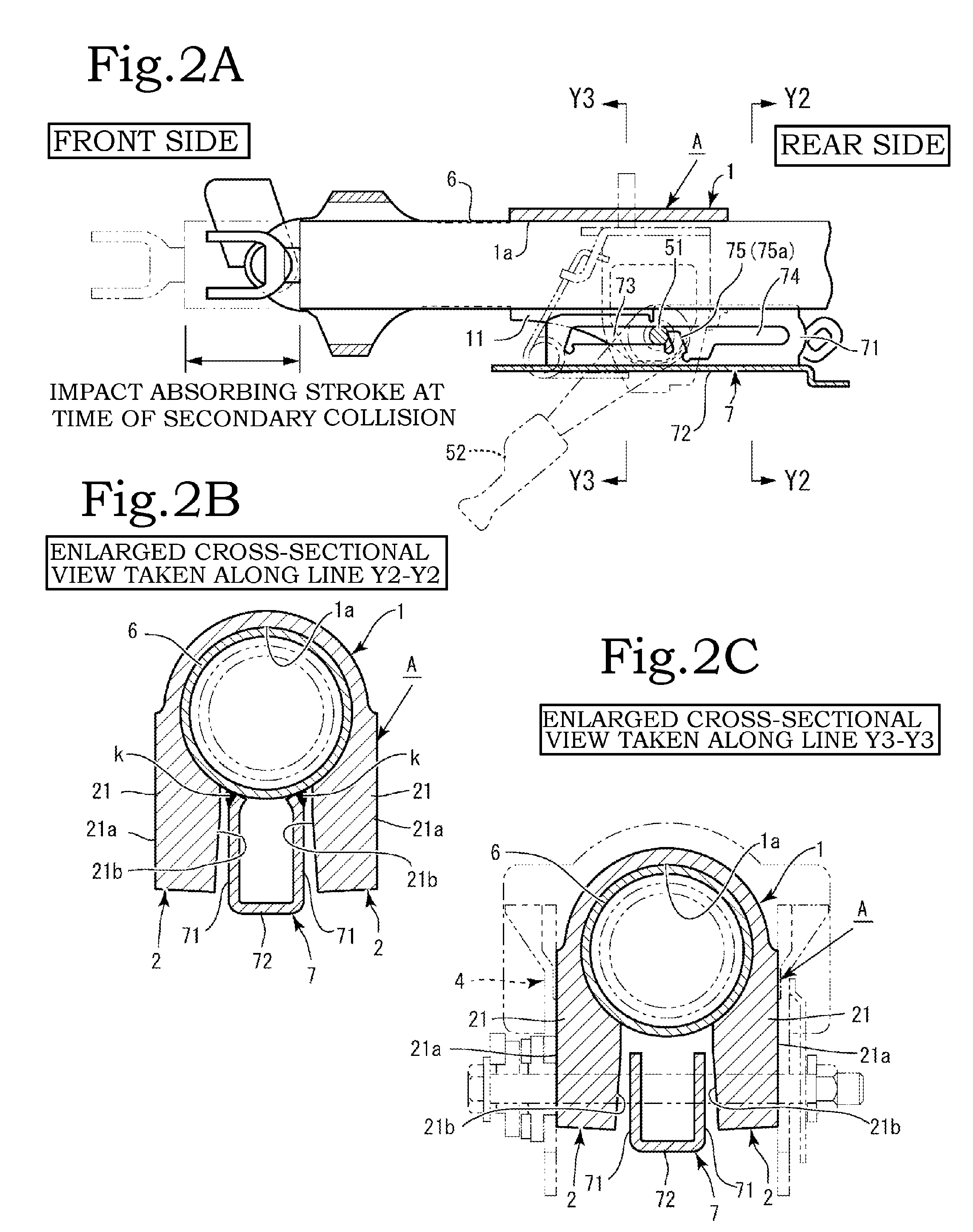
[0075]In a fourth embodiment, the telescopic slot and the impact absorbing slot are formed in the first hanging plate-like portion of the stopper bracket, whereas a slot through which the bolt shaft is freely inserted and is relatively movable is formed in the second hanging plate-like portion. Thus, at the time of a secondary collision, impact absorption is carried out only by the first hanging plate-like portion, enabling smooth impact absorption without causing a time difference in the impact absorbing operation.
[0076]In a fifth embodiment, the partitioning projecting piece formed in the first hanging plate-like portion differs, in axial (front-rear wise) position, from the partitioning projecting piece formed in the second hanging plate-like portion. This enables an increase in the range of adjustment of the peak load. In a sixth embodiment, the partitioning projecting piece of the first hanging plate-like portion differs, in height wise dimension, from the partitioning projecti...
seventh embodiment
[0077]In a seventh embodiment, generally circular cutout-like groove portions are formed at a vehicle body front-side end portion of the telescopic slot and near a vehicle body front-side root of the partitioning projecting piece. Furthermore, a circular base portion of a cushioning member including the base portion and a tail portion extending outward from the base portion is fitted in each of the cutout-like groove portions. Thus, the cushioning member that absorbs an impact during telescopic adjustment can be easily attached to a predetermined position. The tail portion of the cushioning member is normally disposed along the partitioning projecting piece. The tail portion serves to mitigate an impact to reduce an impact sound at the time of a collision between the bolt shaft and the partitioning projecting piece during telescopic adjustment, improving the feel of operating the telescopic adjustment.
[0078]Furthermore, when the car collides, the base portion installed in the genera...
PUM
 Abstract
Description
Claims
Application Information