Fan serial connection structure

a serial connection and fan technology, applied in the direction of machines/engines, mechanical equipment, liquid fuel engines, etc., can solve the problems of high heat generation of internal components of electronic products, inability to change the vibration state of the fan, and high heat generation of the internal components of the electronic products, so as to reduce the vibration of the series fan assembly, improve the reading efficiency of the hard disk, and reduce the vibration. the effect of vibration

Active Publication Date: 2015-08-20
ASIA VITAL COMPONENTS (CHINA) CO LTD
View PDF7 Cites 2 Cited by
  • Summary
  • Abstract
  • Description
  • Claims
  • Application Information

AI Technical Summary

Benefits of technology

[0014]According to the above structural design, the first and second connection members are assembled and connected with the series fan assembly in the serial connection position. In this case, when the series fan operates, the vibration frequencies of the fans of the series fan assembly are unified to offset or damp the co-vibration of the series fan so as to greatly reduce the vibration of the series fan assembly and lower the noise caused by the vibration. In addition, the reading efficiency of the hard disk of the system is enhanced.

Problems solved by technology

In operation, the internal components of the electronic products (such as computers and laptops) will generate high heat.
Otherwise, the problem of overheating will take place.
Therefore, the vibration state of the fan cannot be changed.
The hard disk (such as the hard disk in a server) of the mainframe system of an electronic product is quite sensitive to vibration.
However, the conventional one-piece fan frame 10 can hardly reduce the vibration.
In some more serious cases, the vibration of the motor and the fan impeller 11 will even interfere with the normal work of other electronic components.
This will lead to deterioration of the performance of the system.
Moreover, the resonation is always accompanied by loud noise.
1. The vibration of the fan can be hardly effectively reduced.
2. The vibration of the fan will make loud noise.
3. The reading efficiency of the hard disk of the system is lowered.

Method used


Image

  • Fan serial connection structure
  • Fan serial connection structure
  • Fan serial connection structure

Examples


Embodiment Construction

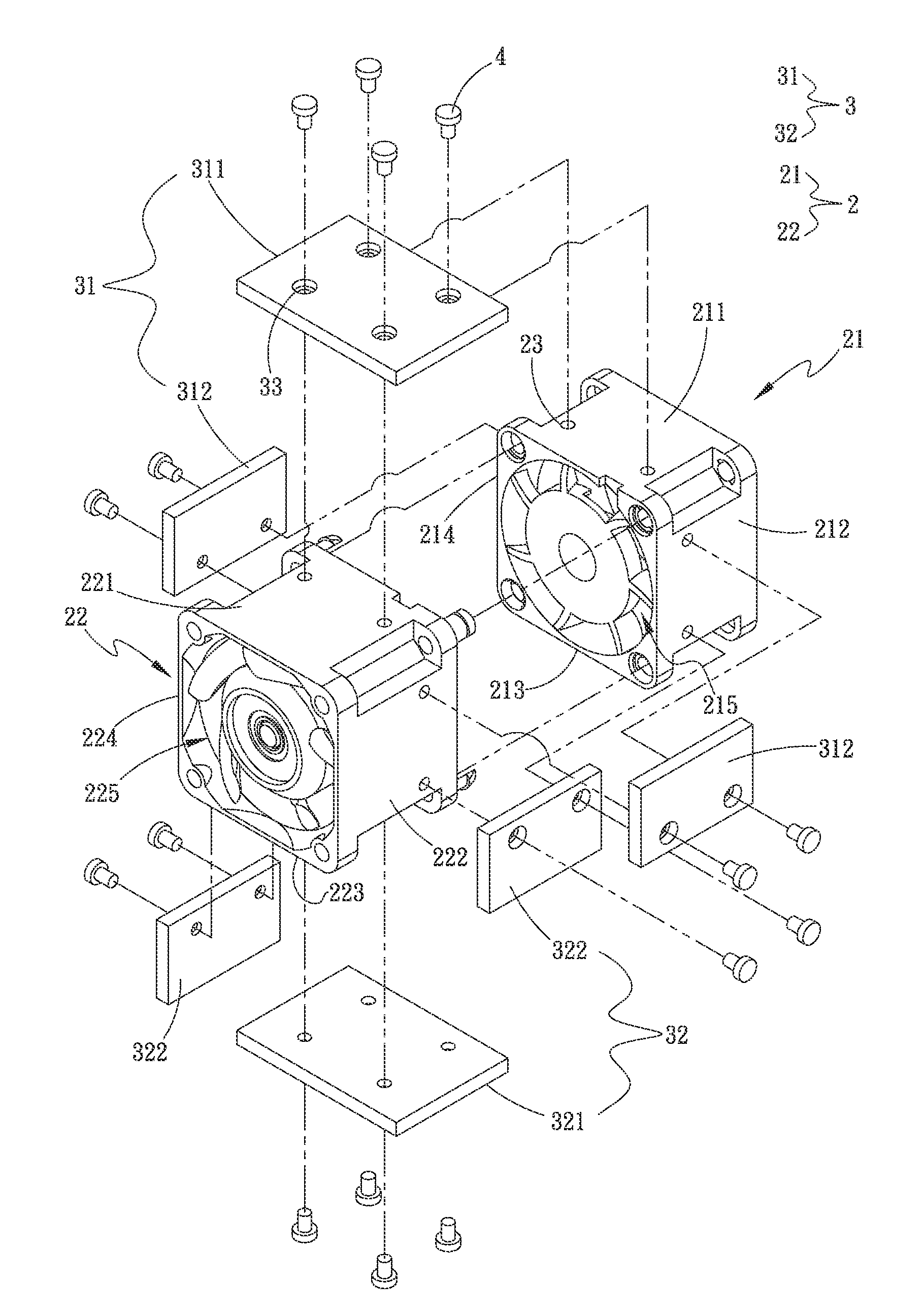
[0024]Please refer to FIGS. 2A and 2B. FIG. 2A is a perspective exploded view of a first embodiment of the fan serial connection structure of the present invention. FIG. 2B is a perspective assembled view of the first embodiment of the fan serial connection structure of the present invention. According to the first embodiment, the fan serial connection structure of the present invention includes a series fan assembly 2 and a connection member assembly 3. The series fan assembly 2 includes a first fan frame 21 and a second fan frame 22 correspondingly serially connected with the first fan frame 21. A first flow passage 215 passes through the first fan frame 21 and a second flow passage 225 passes through the second fan frame 22. The second flow passage 225 correspondingly communicates with the first flow passage 215.

[0025]In this embodiment, the first and second fan frames 21, 22 are serially connected with each other by means of, but not limited to, engagement for illustration purpo...


PUM


Abstract

A fan serial connection structure includes a series fan assembly and a connection member assembly. The series fan assembly includes a first fan frame and a second fan frame serially connected with the first fan frame. The connection member assembly includes a first connection member and a second connection member. The first connection member has a first locating section and two first side sections respectively connected with two ends of the first locating section. The second connection member has a second locating section and two second side sections respectively connected with two ends of the second locating section. The first and second locating sections are respectively assembled and connected with two opposite sides of the series fan assembly in the serial connection position. The first and second side sections are respectively assembled and connected with two other opposite sides of the series fan assembly in the serial connection position.

Description

BACKGROUND OF THE INVENTION[0001]1. Field of the Invention[0002]The present invention relates generally to an improved fan serial connection structure, and more particularly to a fan serial connection structure, which can greatly reduce the vibration of the fan and lower the noise.[0003]2. Description of the Related Art[0004]Along with the continuous advance of sciences and technologies, the reliance of peoples on various electronic apparatuses has more and more increased. In operation, the internal components of the electronic products (such as computers and laptops) will generate high heat. The heat must be dissipated to outer side of the electronic products in time. Otherwise, the problem of overheating will take place. Therefore, most of the electronic products are provided with fans disposed therein for keeping the electronic products working at an operation temperature within a range.[0005]Please refer to FIGS. 1A and 1B. The fan frames 10 of the current series fan 1 have the ...

Claims


Application Information

Patent Timeline
Patent Type & Authority Applications(United States)
IPC IPC(8): F04D29/66F04D29/60
CPCF04D29/601F04D29/668F04D19/007
Inventor LIU, WEN-HAO
Owner ASIA VITAL COMPONENTS (CHINA) CO LTD
Why Eureka
Try Eureka