Detection of the spatial location of an implantable biosensing platform and method thereof

a biosensor and spatial location technology, applied in the field of biosensors, can solve the problems of larger implantable device footprint, aforementioned alignment problem gets further complicated, and the position placement of the external proximity communicator (used for powering and data communication above the skin) becomes difficul

Inactive Publication Date: 2015-08-27
BIORASIS
View PDF6 Cites 664 Cited by
  • Summary
  • Abstract
  • Description
  • Claims
  • Application Information

AI Technical Summary

Benefits of technology

[0008]In one embodiment, the implantable biosensor platform may include bar code type 1-D, and / or QR code type and / or AR code type 2-D patterns (also any other types of bar codes may be used, such as 3-D and image codes etc.) that use reflecting coatings comprised of metals, dielectric mirrors and / or phosphors sensitive to the lighting source that powers the solar cells. The coatings may be located on one of the sub-chips. The imaging may be done by a CCD or MOS camera in the external control unit. Once the implanted biosensor is located and aligned, locking of the position is achieved by energizing the electromagnetic coils located in the external control unit.

Problems solved by technology

Miniature totally implantable biomedical sensing devices have the potential to diagnose and manage a vast array of physiological ailments due to their ability to deliver continuous, real-time sensor readings, as opposed to data collection at periodic user-defined intervals which does not holistically capture the overall trends in biomarkers of interest (such is the case with finger-prick glucose measurements for diabetes management).
However, as the size of the implant gets reduced, the exact location of the implant gets difficult to ascertain, hence the positional placement of the external proximity communicator (used for powering and data communication above the skin) becomes challenging.
The aforementioned alignment issue gets further complicated as both devices (i.e. proximity communicator mostly and to a lesser extend the implanted device) tend to migrate from their initial sites.
The addition of these circuits inherently results in both a larger implantable device footprint as well as an increase in the overall power consumption of the device.

Method used


Image

  • Detection of the spatial location of an implantable biosensing platform and method thereof
  • Detection of the spatial location of an implantable biosensing platform and method thereof
  • Detection of the spatial location of an implantable biosensing platform and method thereof

Examples


Embodiment Construction

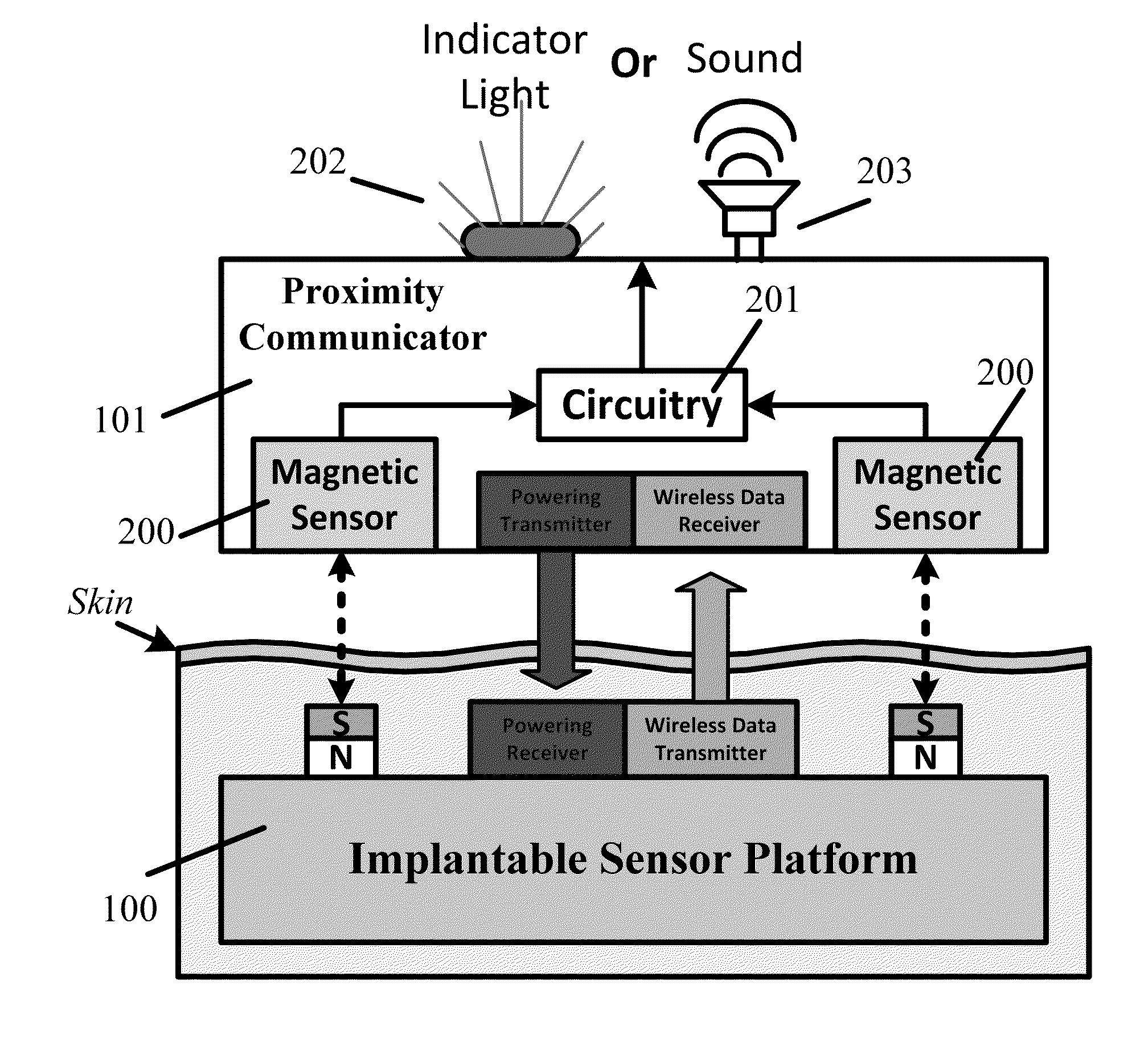
[0028]The present invention provides a methodology to pinpoint the location of a miniaturized implantable biomedical device by integrating the implant with miniature magnets or materials with magnetic properties (such as nano-sized iron particles or other polarized nanomaterials). Once integrated into the implanted platform, the magnetic field generated through the patient's skin can then detected by the proximity communicator unit located externally in a variety of techniques. These techniques can be partitioned into two distinct methodologies, namely: (i) “self-alignment” methodology, which automatically aligns the powering and data communication components on the implantable platform together with the powering and data receiving components on the external communicator unit when both are in close proximity to each other, and (ii) “User-controlled” alignment, wherein the alignment / misalignment of the implantable unit relative to the proximity communicator is relayed to the user via...


PUM


Abstract

A methodology used to pinpoint the location of an implantable biomedical sensing device is provided and is carried out by integrating miniaturized magnets, or materials with magnetic properties into the implantable bio-sensing chip to detect the position of the implant by sensing the induced magnetic field via an external communication unit. Presented here are various configurations in which magnetic positional detection can be carried out. The positional information collected from these detection motifs can be used to provide feedback to the user about alignment status as well as activate a self-alignment methodology. With respect to the former, based on the positional information received the user manually adjusts the location of the external communicator into place to align with the implantable platform. In the latter scenario, various configurations allow the wireless powering and communication components on the proximity communicator to automatically find and align with the implantable biomedical sensing chip.

Description

CROSS REFERENCE TO RELATED APPLICATIONS[0001]This application claims the benefit of priority of the filing date of U.S. Provisional Patent Application Ser. No. 61 / 945,542 filed Feb. 27, 2014, the contents of which is incorporated herein by reference in its entirety.STATEMENT REGARDING FEDERALLY SPONSORED RESEARCH[0002]The United States Government has certain rights in this invention pursuant to National Institute of Health Grant No. 1R43EB011886 and National Science Foundation Grant No. 1230148.FIELD OF THE INVENTION[0003]This invention relates generally to biosensors and more particularly to detecting and locating the position of a biosensor that has been implanted into a subject.BACKGROUND OF THE INVENTION[0004]Miniature totally implantable biomedical sensing devices have the potential to diagnose and manage a vast array of physiological ailments due to their ability to deliver continuous, real-time sensor readings, as opposed to data collection at periodic user-defined intervals ...

Claims


Application Information

Patent Timeline
Patent Type & Authority Applications(United States)
IPC IPC(8): A61B5/06A61B5/145
CPCA61B5/062A61B5/14532A61B5/14503A61B5/0017A61B5/1114
Inventor LEGASSEY, ALLENCROCE, JR., ROBERT A.VADDIRAJU, SANTHISAGARJAIN, FAQUIR C.PAPADIMITRAKOPOULOS, FOTIOS
Owner BIORASIS
Why Eureka
Try Eureka