
System and method for performing bi-plane tomographic acquisitions

a tomographic and bi-plane technology, applied in tomography, instruments, applications, etc., can solve the problems of bulk of certain systems, such as x-ray computed tomography systems, preventing their use in conjunction with medical procedures, and affecting the accuracy of tomographic acquisition results

Active Publication Date: 2015-08-27
GENERAL ELECTRIC CO
View PDF3 Cites 37 Cited by
  • Summary
  • Abstract
  • Description
  • Claims
  • Application Information

AI Technical Summary

Benefits of technology

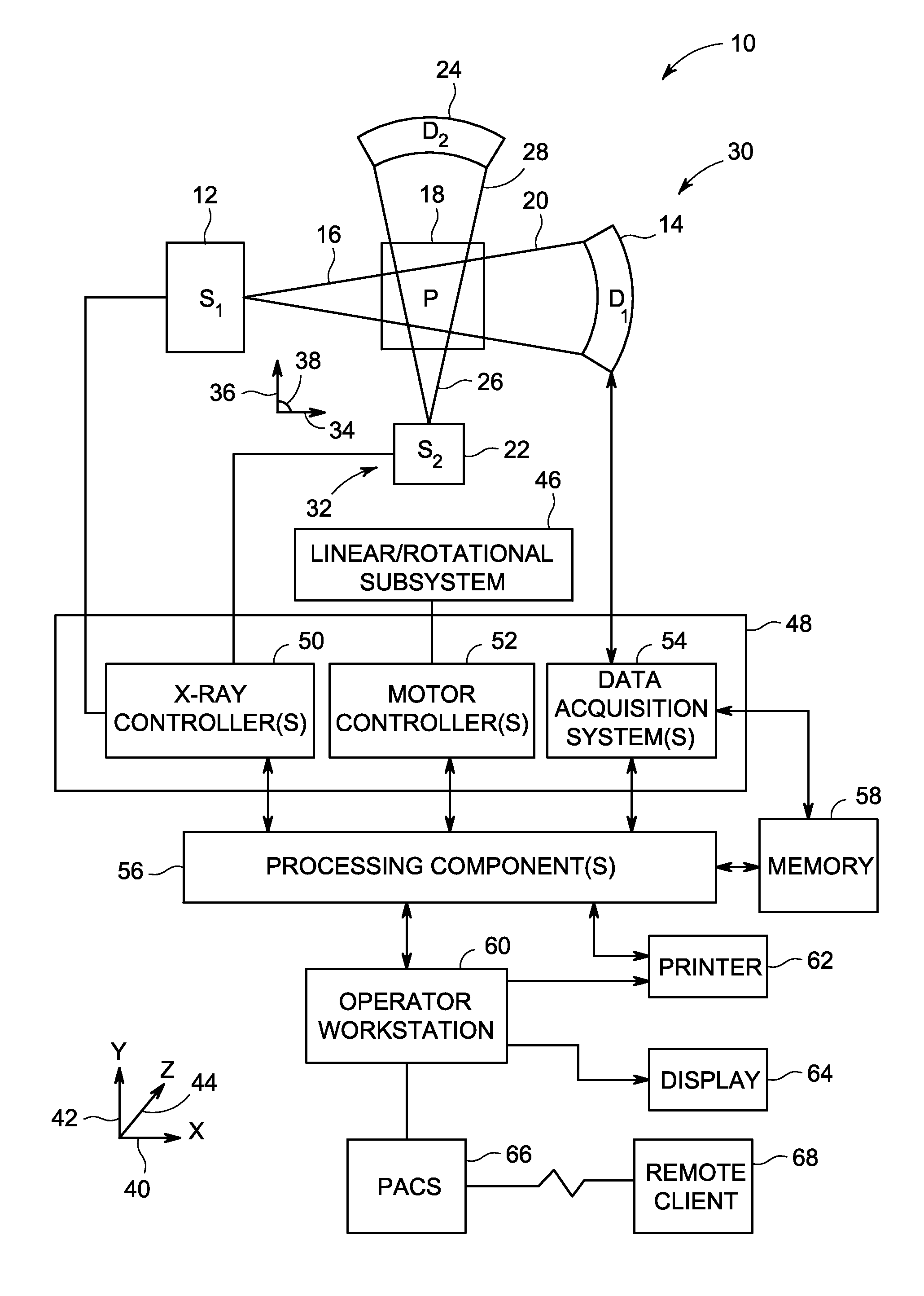
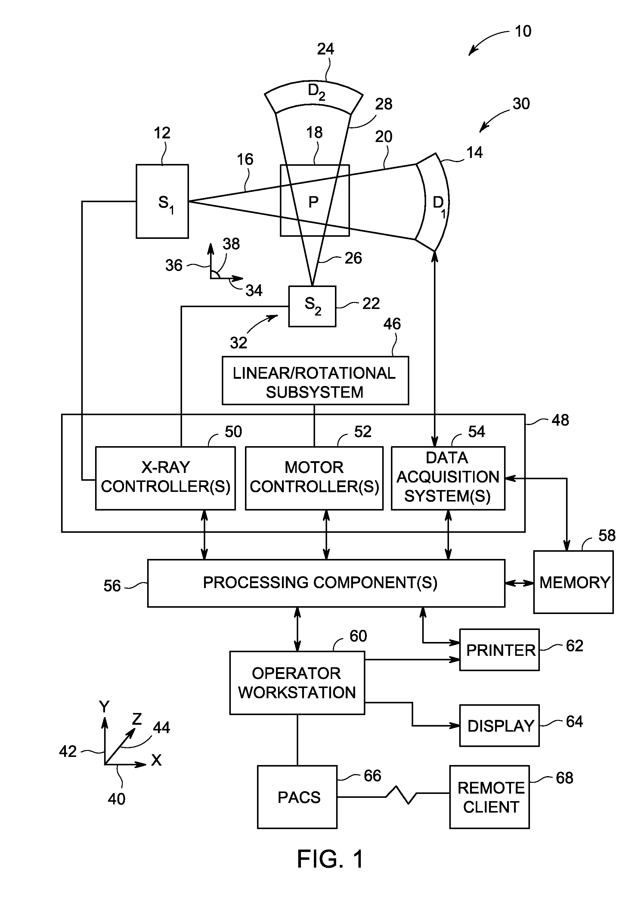
The patent describes a medical imaging system that can generate a volumetric image of an imaged volume by moving a first X-ray source and a first X-ray detector in a non-linear trajectory while obtaining X-ray attenuation data from the imaged volume. The system also includes a second X-ray imager that can obtain additional X-ray attenuation data from the same imaged volume. The two sets of data are then combined to create the volumetric image using tomosynthesis. The technical effect of this system is improved image quality and accuracy in the detection and diagnosis of medical abnormalities.

Problems solved by technology

However, various physical limitations or constraints on acquisition may result in artifacts or other imperfections in the reconstructed image.
Furthermore, the bulk of certain systems, such as X-ray computed tomography systems, can preclude their use in conjunction with medical procedures, such as interventional procedures.
With respect to the resultant images obtained by certain X-ray systems, imaging methods that utilize X-ray projection images may suffer from artifacts due to incompleteness of the scan data.
Truncation of data in certain directions (e.g., in the direction corresponding to the one or more axes about which the X-ray source rotates about the patient), mishandled data, and / or missing projection angles can often lead to such artifacts and imperfections.
In addition, obtaining complete data sets can be time-consuming.

Method used


Image

  • System and method for performing bi-plane tomographic acquisitions
  • System and method for performing bi-plane tomographic acquisitions
  • System and method for performing bi-plane tomographic acquisitions

Examples


Embodiment Construction

[0021]One or more specific embodiments will be described below. In an effort to provide a concise description of these embodiments, all features of an actual implementation may not be described in the specification. It should be appreciated that in the development of any such actual implementation, as in any engineering or design project, numerous implementation-specific decisions must be made to achieve the developers' specific goals, such as compliance with system-related and business-related constraints, which may vary from one implementation to another. Moreover, it should be appreciated that such a development effort might be complex and time consuming, but would nevertheless be a routine undertaking of design, fabrication, and manufacture for those of ordinary skill having the benefit of this disclosure.

[0022]When introducing elements of various embodiments of the present invention, the articles “a,”“an,”“the,” and “said” are intended to mean that there are one or more of the ...


PUM


Abstract

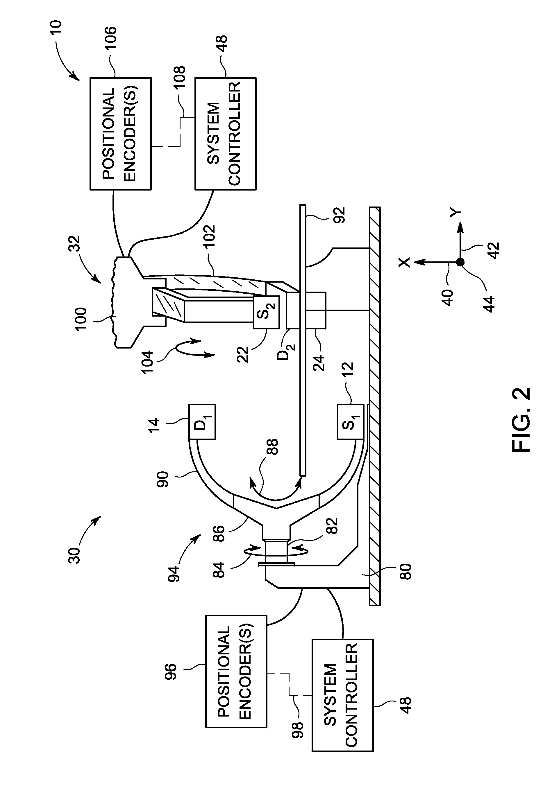
A method includes, in a bi-plane interventional imaging system, moving a first C-arm supporting a first X-ray source and a first X-ray detector about first and second axes while obtaining a plurality of first X-ray attenuation data sets relating to a subject of interest; moving a second C-arm, positioned crosswise with respect to the first C-arm and supporting a second X-ray source and a second X-ray detector, about the first axis while obtaining a plurality of second X-ray attenuation data sets relating to the subject of interest; and synchronizing the movement of the first and second C-arms to avoid collision therebetween.

Description

BACKGROUND[0001]The subject matter disclosed herein relates to tomographic imaging and, more particularly, to performing tomographic imaging using data generated from two imaging planes.[0002]Imaging technologies allow images of the internal structures of a patient or object to be obtained, thereby minimizing the invasive procedure on the patient or object. In particular, technologies such as X-ray fluoroscopy, X-ray computed tomography (CT), and tomosynthesis use various physical principles, such as the varying transmission of X-rays through a target volume, to acquire projection data and to construct images (e.g., three-dimensional, volumetric representations of the interior of the human body or of other imaged structures). However, various physical limitations or constraints on acquisition may result in artifacts or other imperfections in the reconstructed image. Furthermore, the bulk of certain systems, such as X-ray computed tomography systems, can preclude their use in conjunc...

Claims


Application Information

Patent Timeline
IPC IPC(8): A61B6/00A61B6/03
CPCA61B6/5258A61B6/035A61B6/482A61B6/4014A61B6/025A61B6/4441
Inventor AL ASSAD, OMARLANGAN, DAVID ALLENCLAUS, BERNHARD ERICH HERMANNEBERHARD, JEFFREY WAYNEGRIMAUD, MICHEL FRANCOIS
Owner GENERAL ELECTRIC CO
Learn More