Vehicle seat

Active Publication Date: 2015-08-27
TOYOTA JIDOSHA KK
View PDF19 Cites 31 Cited by
  • Summary
  • Abstract
  • Description
  • Claims
  • Application Information

AI Technical Summary

Benefits of technology

[0015]According to an aspect and an embodiment of the present invention, it is possible to improve steering operability in a driver's seat, and to improve posture maintaining capability at the time of turning in the driver's seat and a seat other than the driver's seat.

Problems solved by technology

However, the vehicle seat disclosed in Japanese Unexamined Patent Application Publication No. 2010-089582 does not consider posture maintaining capability at this time of turning.

Method used


Image

  • Vehicle seat
  • Vehicle seat
  • Vehicle seat

Examples


first embodiment

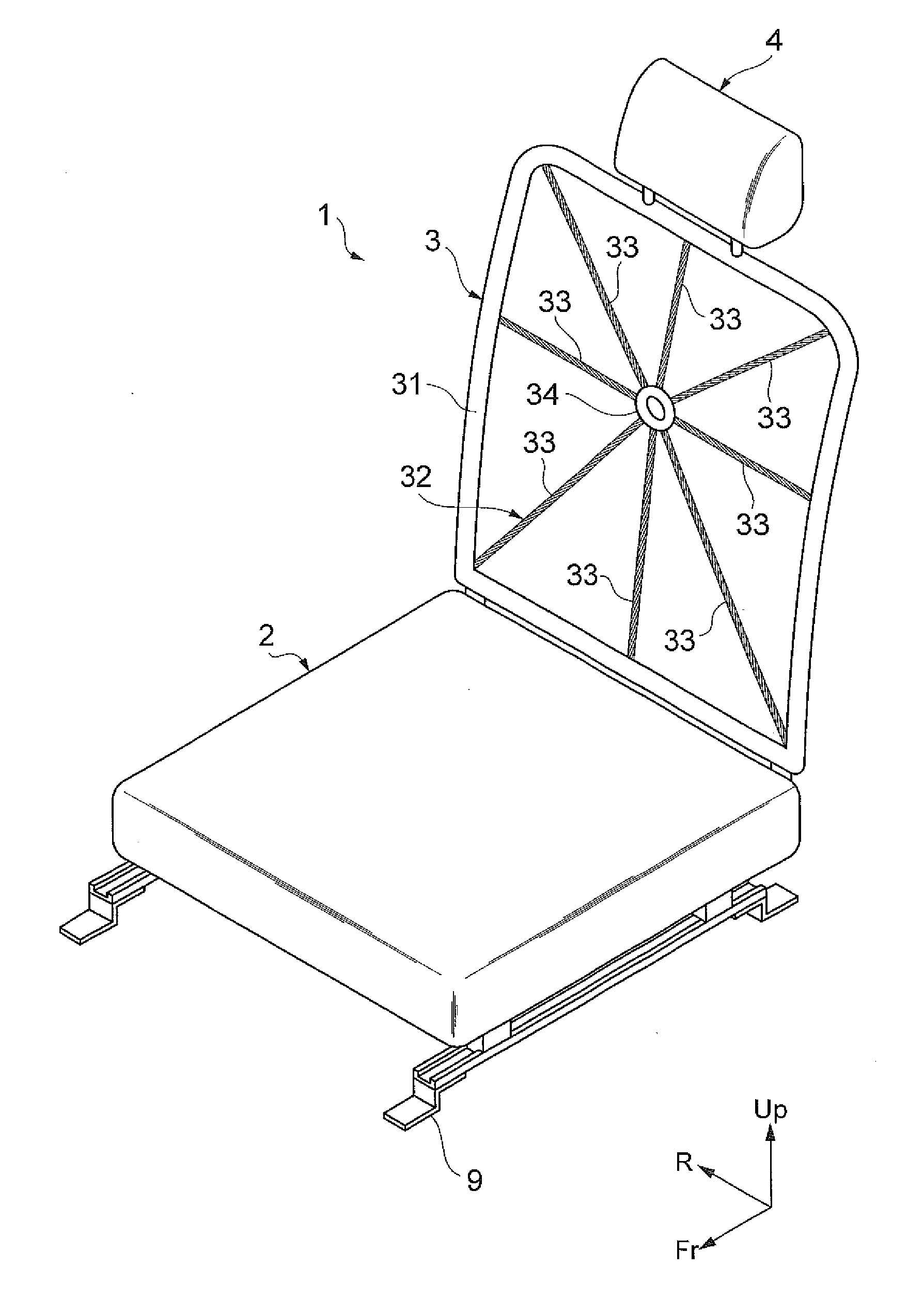
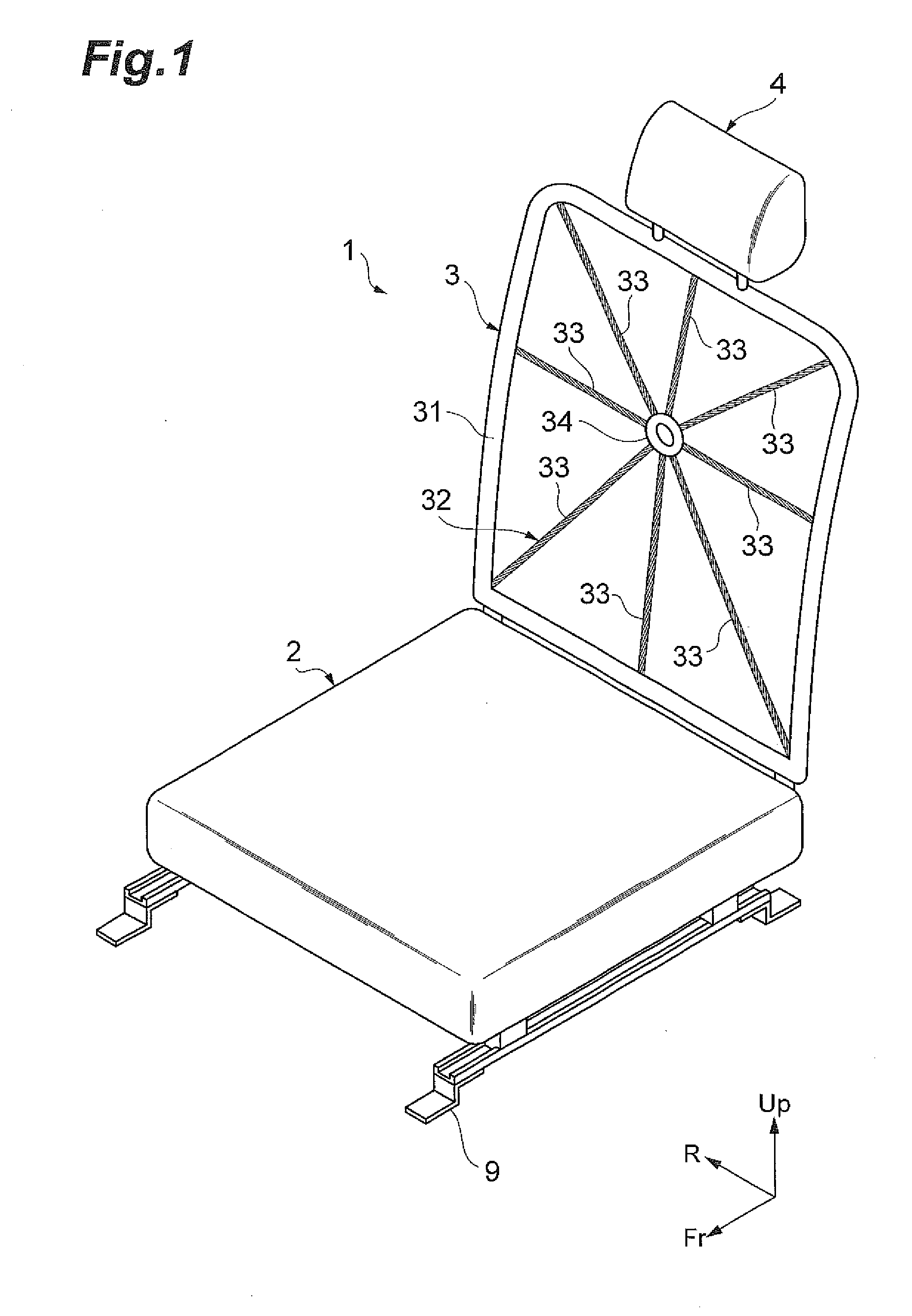
[0041]FIG. 1 is a perspective view illustrating the vehicle seat according to a first embodiment. As illustrated in FIG. 1, the vehicle seat 1 according to the first embodiment is slidably attached to a rail 9 fixed onto a floor of the vehicle. A vehicle seat 1 includes a seat 2 on which the pelvis and the thighbone of the vehicle occupant are placed when the vehicle occupant sits thereon, a seat backrest 3 which supports the back of the vehicle occupant from behind the vehicle occupant, and a headrest 4 which supports the head of the vehicle occupant from behind the vehicle occupant. The seat backrest 3 is connected to a rear end part of the seat 2, and the headrest 4 is connected to an upper end part of the seat backrest 3.

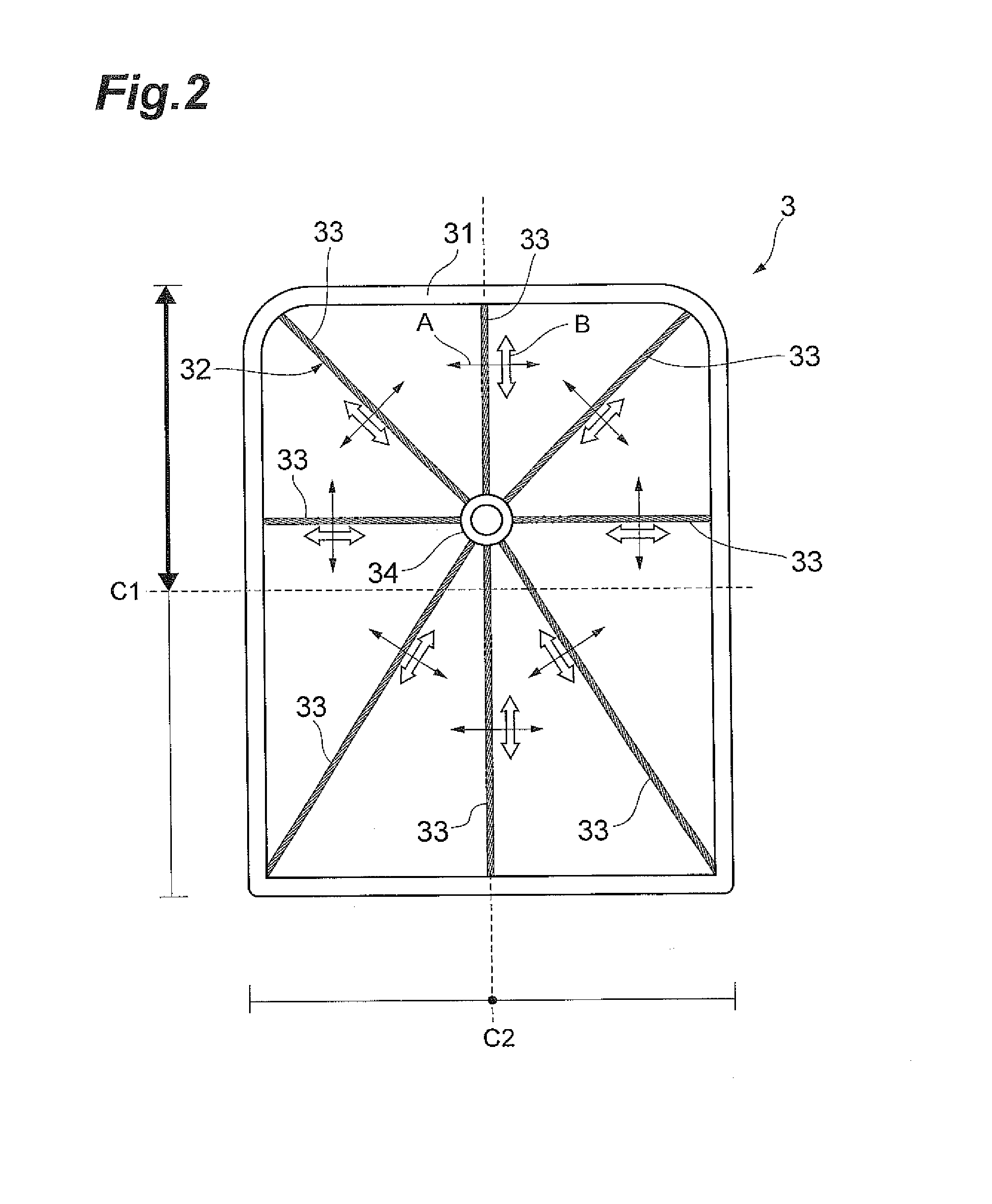
[0042]FIG. 2 is a front view of the seat backrest. As illustrated in FIGS. 1 and 2, the seat backrest 3 includes a seat backrest frame 31 formed in a frame shape and a net 32 disposed to stretch in the seat backrest frame 31.

[0043]The seat backrest frame 31 is a...

second embodiment

[0058]Next, a second embodiment will be described. The second embodiment is basically the same as the first embodiment, but is different from the first embodiment in that the net is configured to have the first string portion and the second string portion. Therefore, in the following description, points different from those in the first embodiment will be described, and thus the same description as that in the first embodiment will be omitted.

[0059]FIG. 13 is a side view illustrating a vehicle seat according to the second embodiment. As illustrated in FIG. 13, a vehicle seat 1A according to the second embodiment includes the seat 2 the same as that in the first embodiment, a seat backrest 3A corresponding to the seat backrest 3 in the first embodiment, and the headrest 4 the same as that in the first embodiment.

[0060]FIG. 14 is a front view of the seat backrest. As illustrated in FIGS. 13 and 14, the seat backrest 3A includes the seat backrest frame 31 the same as that in the first ...

third embodiment

[0068]Next, a third embodiment will be described. The third embodiment is basically the same as the first embodiment, but is different from the first embodiment in that the seat is configured to be pivotally movable. Therefore, in the following description, points different from those in the first embodiment will be described, and thus description the same as that in the first embodiment will be omitted.

[0069]FIG. 17 is a perspective view illustrating a vehicle seat according to the third embodiment. FIG. 18 is a side view illustrating the vehicle seat according to the third embodiment. FIG. 19 is a front view illustrating the vehicle seat according to the third embodiment. As illustrated in FIGS. 17 to 19, a vehicle seat 1B according to the third embodiment includes a seat 2B in place of the seat 2 in the first embodiment, the seat backrest 3 the same as that in the first embodiment, and the headrest 4 the same as that in the first embodiment.

[0070]A seat frame 51 for supporting th...


PUM


Abstract

To improve steering operability in a driver's seat, and to improve posture maintaining capability at the time of turning in the driver's seat and a seat other than the driver's seat. In a vehicle seat including a seat, a seat backrest, and a headrest, the seat backrest has a seat backrest frame formed in a frame shape and a net disposed to stretch in the seat backrest frame. The net has a first string portion arranged radially.

Description

BACKGROUND OF THE INVENTION[0001]1. Field of the Invention[0002]The present invention relates to a vehicle seat mounted on a vehicle.[0003]2. Related Background Art[0004]A vehicle seat disclosed in Japanese Unexamined Patent Application Publication No. 2010-089582 has a configuration in which a mesh-shaped (lattice-shaped) net is disposed to stretch in a pair of frame members of a seat backrest so that a bending provider for bending the net is attached to a rear surface of the net. In this manner, the net is bent by the bending provider so as to have a shape which fits a body shape of a user. As a result, a sense of fit felt by the user for the net is improved, and a pressure difference partially decreases between the net and the user, thereby allowing a seat to be comfortable when the user is seated.[0005]Incidentally, when a driver sitting on a vehicle seat serving as a driver's seat performs a steering operation using a steering wheel, a vehicle occupant tries to pivotally move h...

Claims


Application Information

Patent Timeline
Patent Type & Authority Applications(United States)
IPC IPC(8): B60N2/68B60N2/50B60N2/70
CPCB60N2/68B60N2/502B60N2/70B60N2/39B60N2/7094B60N2002/0208A47C7/22A47C7/32B60N2/682B60N2/7011B60N2/72B60N2002/684B64D11/06B64D11/0649B64D11/0691
Inventor HAMABE, TSUTOMUKATOH, KOHSHI
Owner TOYOTA JIDOSHA KK
Why Eureka
Try Eureka