

Ball screw and steering apparatus
a technology of ball screw and steering apparatus, which is applied in the direction of mechanical equipment, transportation and packaging, etc., can solve problems such as noise of collision
Inactive Publication Date: 2015-08-27
SHOWA CORP
View PDF9 Cites 5 Cited by
- Summary
- Abstract
- Description
- Claims
- Application Information
AI Technical Summary
Benefits of technology
This patent aims to solve the problem of collision noise between the ball and the end deflector and guiding tip edge when the ball enters the end deflector from a helical groove of a screw shaft. By forming a gap between the ball and the helical groove and guiding the ball with a shallow angle, the collision noise can be reduced. This technology improves the performance of the ball screw and steering apparatus.
Problems solved by technology
That is, there is a problem in that a step is formed between the guiding protrusion portion and the helical groove of the screw shaft, and thus collision noise occurs when the ball comes out of the helical groove of the screw shaft, and is brought into contact with the step.
Method used
View moreImage
Smart ImageViewing Examples

Examples
modification example
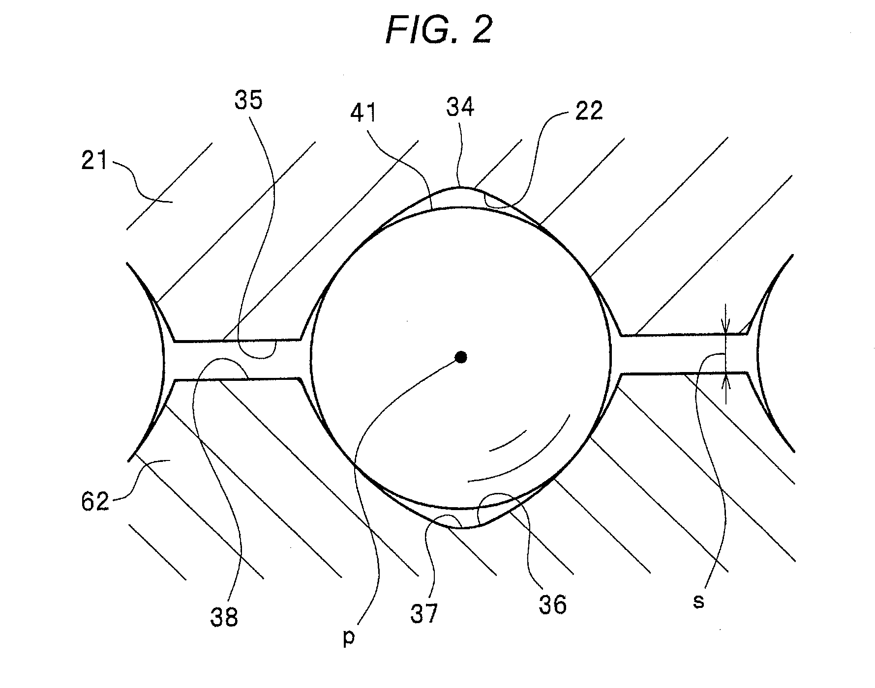
[0053]In the embodiment, the groove side surface positioned on the outer side in the direction of the axis O functions as one groove side surface 75A along which the ball 41 is lifted. In contrast, the groove side surface positioned on the inner side in the direction of the axis O may function as one groove side surface 75A. In this case, the path 18 of the end deflector 2 is formed in such a manner that the first path 18A is joined with the second path 18B while inclining toward the inner side in the direction of the axis O.
Login to View More PUM
 Abstract
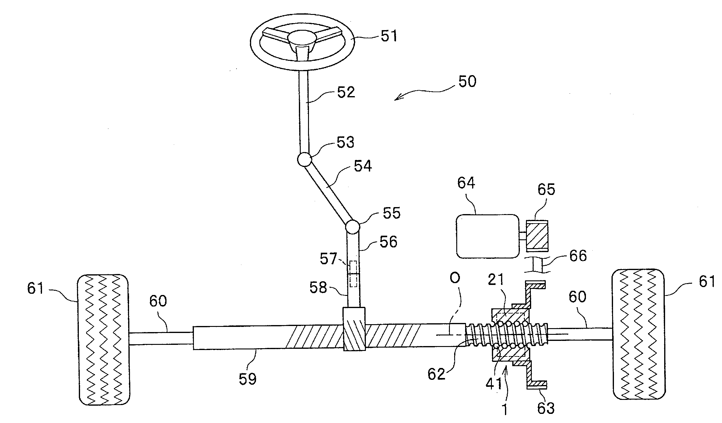
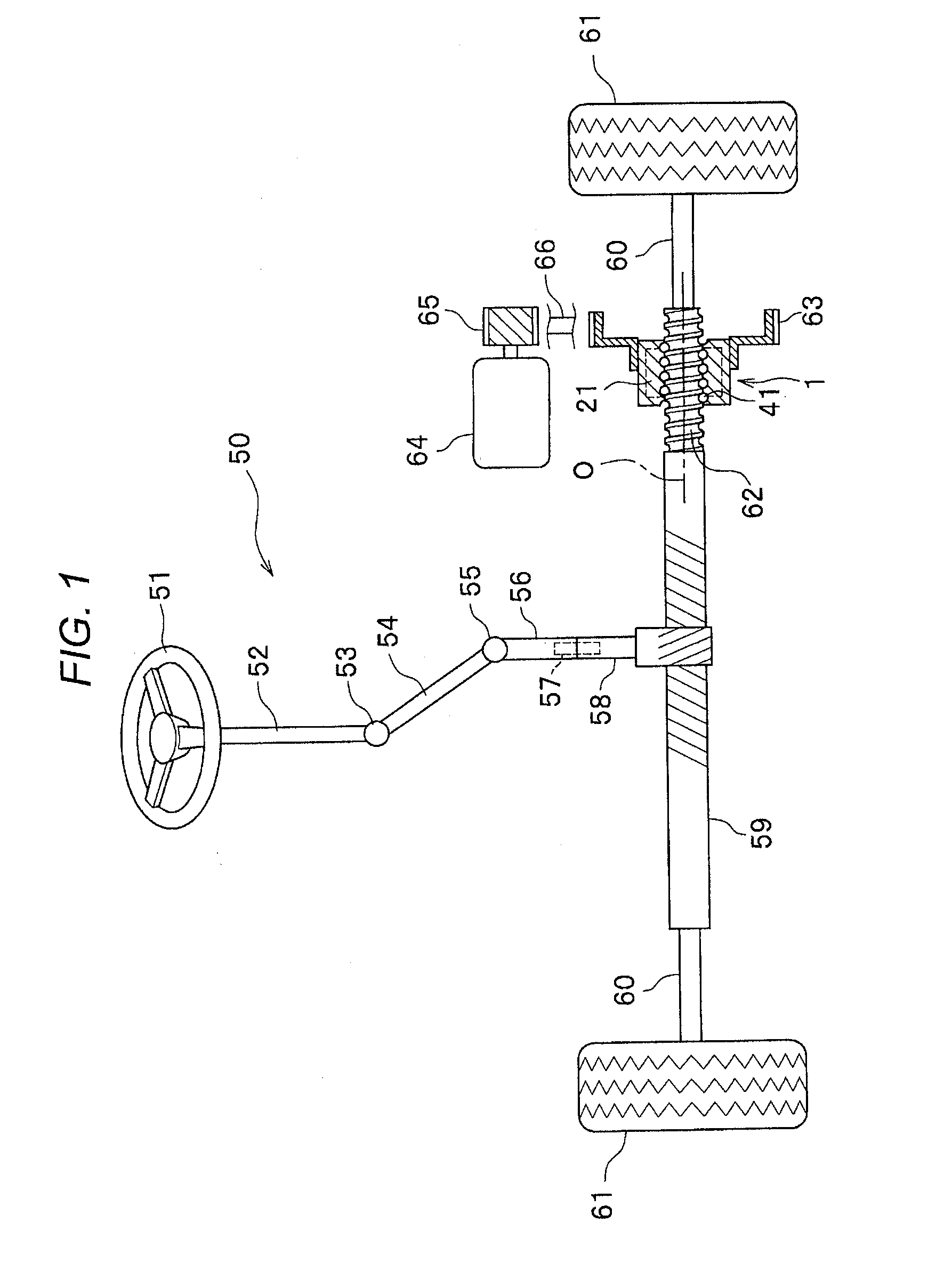
A ball screw includes: a nut; a screw shaft; and an end deflector that is attached to the nut, and has a guiding protrusion portion which protrudes toward a helical groove of the screw shaft, in which a guiding tip edge of the guiding protrusion portion picks up a ball and guides the ball into the end deflector, the end deflector includes a ball lifting portion that lifts the ball along one groove side surface of the helical groove, and the guiding tip edge picks up the ball lifted by the ball lifting portion.
Description
CROSS-REFERENCE TO RELATED APPLICATIONS[0001]This application is based on and claims priority under 35 USC 119 from Japanese Patent Application No. 2014-034821 filed on Feb. 26, 2014, the entire content of which is incorporated herein by reference.BACKGROUND OF THE INVENTION[0002]1. Technical Field[0003]The present invention relates to a ball screw and a steering apparatus.[0004]2. Related Art[0005]There is a method in which an end deflector is adopted so as to circulate a ball screw. In this method, a circulation path is formed in a nut so as to circulate a ball. The end deflector is attached to each end of the nut so as to guide the ball to the circulation path from the nut and a helical groove of a screw shaft, or to return the ball to the helical groove from the circulation path (refer to Patent Literature 1 (JP-A-2012-154437)). The end deflector has a guiding protrusion portion (a claw in Patent Literature 1) that protrudes into the helical groove of the screw shaft so as to pi...
Claims
Login to View More Application Information
Patent Timeline
 Patent Type & AuthorityApplications(United States)
IPC IPC(8): B62D5/04B62D3/08
CPCB62D3/08B62D5/0448B62D3/06F16H25/2204F16H25/2219Y10T74/18576F16H2025/2242
InventorITO, RYOTA
OwnerSHOWA CORP