Electromechanical brake amplifier

A braking force, electromechanical technology, applied in the direction of brakes, brake safety systems, brake transmissions, etc., can solve problems such as load and noise generation

Pending Publication Date: 2021-10-22
ROBERT BOSCH GMBH
View PDF1 Cites 0 Cited by
  • Summary
  • Abstract
  • Description
  • Claims
  • Application Information

AI Technical Summary

Problems solved by technology

As a result, the driver element hits the hook bracket, which can lead to a load on the hook...

Method used


Image

  • Electromechanical brake amplifier
  • Electromechanical brake amplifier
  • Electromechanical brake amplifier

Examples


Embodiment Construction

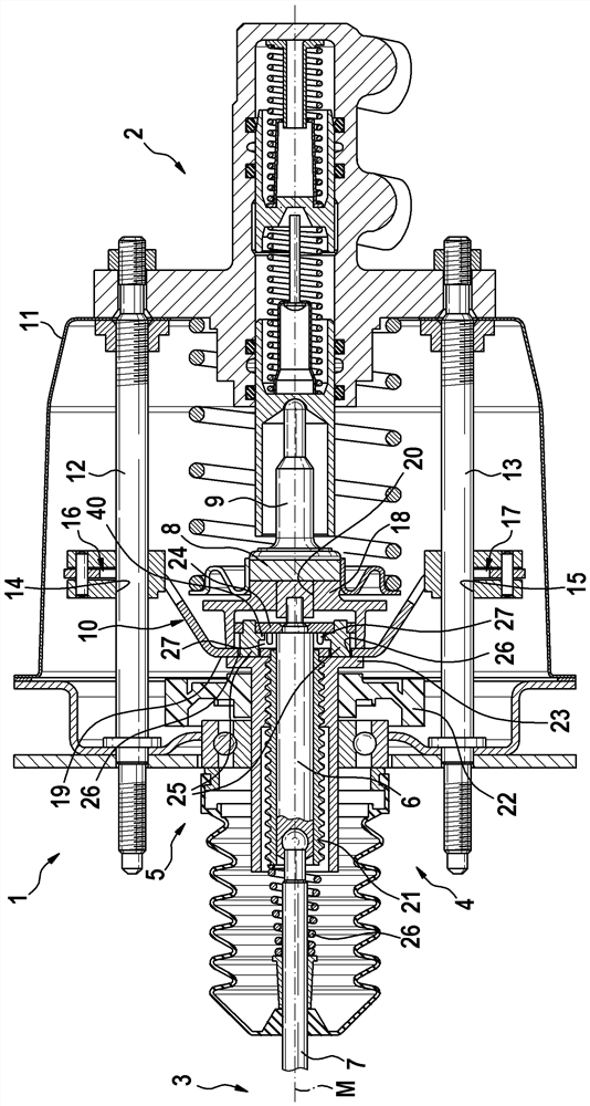
[0020] figure 1An advantageous brake booster 1 is shown in a simplified longitudinal section. Brake booster 1 can be coupled at one end to brake master cylinder 2 and at the other end to a brake pedal 3 of the motor vehicle, not shown here. Brake booster 1 serves to adjust the hydraulic pressure in master brake cylinder 2 as a function of brake pedal actuation. For this purpose, the brake booster 1 has an actuator 4 with an electric motor not shown and a spindle drive 5 via which the torque of the electric motor can be applied to the brake as thrust. On the connecting part of the moving pedal 3 and the brake master cylinder 2.

[0021] The brake booster 1 has a pressure piston 6 which is assigned to the brake master cylinder 2 at one end and is mechanically coupled at the other end to a coupling rod 7 which is connected to the brake It is connected with the brake pedal 3, and is moved by the operation of the brake pedal 3. One end of the pressure piston 6 is assigned to an...


PUM


Abstract

A brake amplifier having a housing; a spindle nut; a motor; two tie rods; a hook frame; and a pressure piston which can be coupled at a first end to a brake pedal and at a second end to a brake master cylinder. A return spring is assigned to the pressure piston which bears a follower element at the second end, which follower element engages the hook frame at the rear and rests on the end side of the spindle nut in a rest position by means of a distance holder passing through the hook frame such that the follower element is spaced apart from the hook frame. In the operating position, the pressure piston is moved relative to the main shaft so that the follower element is spaced from the hook frame and is spaced from the end side by means of the distance holder. An elastomer element projecting axially in the direction of the hook frame is arranged on the side of the follower element facing the hook frame, and/or an elastomer element projecting axially in the direction of the follower element is arranged on the end side of the hook frame facing the follower element.

Description

technical field [0001] The invention relates to an electromechanical brake booster for a vehicle, having a housing; a rotatably mounted spindle nut, which is operatively engaged with an axially displaceable spindle; an electric motor for rotating drive the spindle nut to move the spindle; two tie rods fastened to the housing and extending parallel to the spindle; a hook frame fastened to the spindle and slidably supported on and a pressure piston extending through the main shaft and movable relative to the main shaft, the pressure piston can be coupled with the brake pedal at the first end, and at the second end The pressure piston is coupled at both ends to the brake master cylinder, and a return spring is assigned to the pressure piston, wherein the pressure piston carries a driver element at the second end, which engages at the rear The hook bracket, and in the rest position with at least one spacer that passes through the hook bracket, rests against the end face of the sp...

Claims


Application Information

Patent Timeline
IPC IPC(8): B60T13/74B60T17/22
CPCB60T13/741B60T17/22B60T13/745
Inventor E·普蒙塔尔A·洛佩斯甘杜尔M·米勒T·埃格尔
Owner ROBERT BOSCH GMBH
Why Eureka
Try Eureka