Zoom lens and imaging apparatus

a zoom lens and imaging apparatus technology, applied in the field of zoom lenses and imaging apparatuses, can solve the problems of increasing the number of lenses forming increasing the size and weight of the first lens group, and achieving the effect of high optical performan

Active Publication Date: 2015-08-27
FUJIFILM CORP
View PDF4 Cites 12 Cited by
  • Summary
  • Abstract
  • Description
  • Claims
  • Application Information

AI Technical Summary

Benefits of technology

[0018]The lens system according to the invention consists of, in order from the object side, a positive fixed group, a moving group consisting of a plurality of lens groups, and a positive fixed group, wherein the most object-side positive fixed group consists of three lens groups and only the middle lens group among the three lens groups functions as a focus gro

Problems solved by technology

The necessity of forming the first lens group by three lens groups and achieving successful correction of aberrations, such as spherical aberration, on the tel

Method used


Image

  • Zoom lens and imaging apparatus
  • Zoom lens and imaging apparatus
  • Zoom lens and imaging apparatus

Examples


example 1

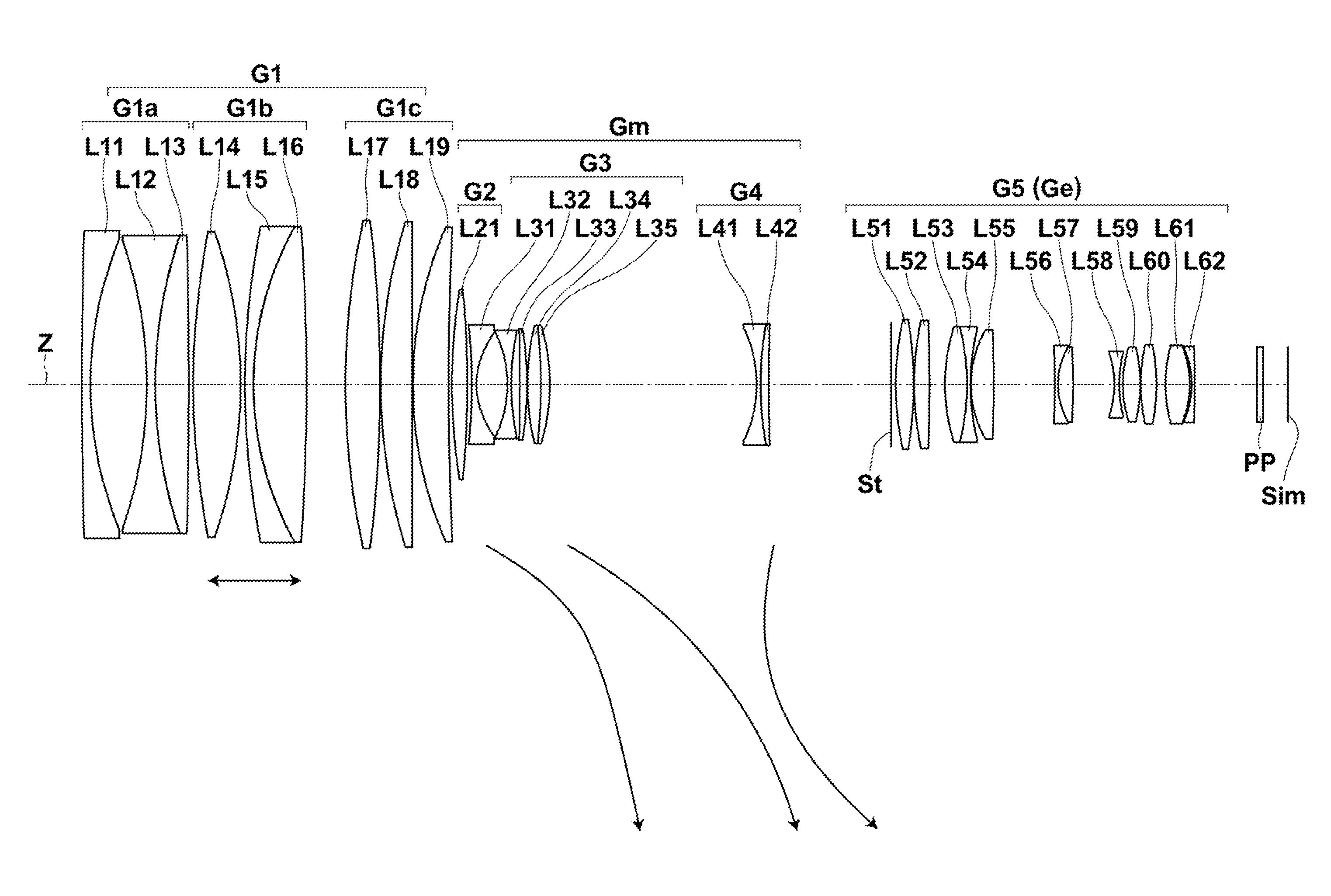
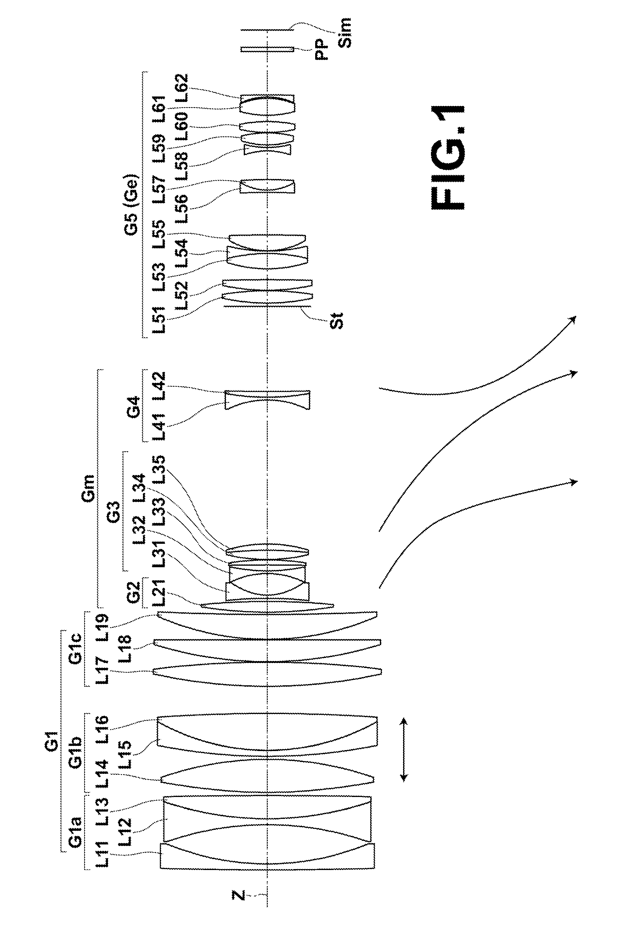
[0069]FIG. 4 is a sectional view illustrating the lens configuration of a zoom lens of Example 1 when the zoom lens is focused on an object at infinity. In FIG. 4, the state at the wide-angle end is shown at the top denoted by the text “WIDE”, the state at the middle focal length is shown at the middle denoted by the text “MIDDLE”, and the state at the telephoto end is shown at the bottom denoted by the text “TELE”. On FIG. 4, the left side is the object side, and the right side is the image side.

[0070]The schematic configuration of the zoom lens of Example 1 is as follows. The zoom lens of Example 1 consists essentially of five lens groups consisting of, in order from the object side, a first lens group G1 having a positive refractive power, a second lens group G2 having a positive refractive power, a third lens group G3 having a negative refractive power, a fourth lens group G4 having a negative refractive power, an aperture stop St, and a fifth lens group G5 having a positive ref...

example 2

[0080]FIG. 5 is a sectional view illustrating the lens configuration of a zoom lens of Example 2 when the zoom lens is focused on an object at infinity. The schematic configuration of the zoom lens of Example 2 is almost similar to that of Example 1, except that, in the zoom lens of Example 2, the first lens-group middle group G1b consists of two lens groups, i.e., a first lens-group middle-group front part G1bf and a first lens-group middle-group rear part G1br, where the first lens-group middle-group front part G1bf and the first lens-group middle-group rear part G1br are moved along the optical axis direction to change an air space therebetween during focusing. The first lens-group front group G1a consists of lenses L11 to L13 in this order from the object side, the first lens-group middle-group front part G1bf consists of a lens L14, the first lens-group middle-group rear part G1br consists of lenses L15 to L16 in this order from the object side, and the first lens-group rear gr...

example 3

[0083]FIG. 6 is a sectional view illustrating the lens configuration of a zoom lens of Example 3 when the zoom lens is focused on an object at infinity. The schematic configuration of the zoom lens of Example 3 is almost similar to that of Example 1, except that, in the zoom lens of Example 3, the first lens-group middle group G1b consists of lenses L14 to L17 in this order from the object side, the first lens-group rear group G1c consists of lenses L18 to L19 in this order from the object side, and the lens L15 is the only aspheric lens included in the first lens-group middle group G1b. The object-side surface of the lens L15 is an aspheric surface, and the image-side surface of the lens L15 is a spherical surface.

[0084]Tables 7, 8, and 9 show basic lens data, specifications and variable surface distances, and aspheric coefficients of the zoom lens of Example 3. In Table 9, “-” is shown, in place of a numerical value, where no aspheric coefficient is present.

TABLE 7Example 3 - Basi...


PUM


Abstract

A zoom lens consists essentially of, in order from the object side: a positive first lens group that is fixed during magnification change; a moving lens group consisting of at least two lens groups that are moved along the optical axis direction to change an air space therebetween during magnification change; a stop; and a positive end lens group that is fixed during magnification change. The first lens group consists of, in order from the object side, a negative first lens-group front group, a positive first lens-group middle group, and a positive first lens-group rear group. During focusing, only the first lens-group middle group is moved along the optical axis direction. The first lens-group middle group includes at least one aspheric lens that satisfies predetermined condition expressions.

Description

CROSS-REFERENCE TO RELATED APPLICATIONS[0001]The present application claims priority under 35 U.S.C. §119 to Japanese Patent Application No. 2014-034897, filed on Feb. 26, 2014. The above application is hereby expressly incorporated by reference, in its entirety, into the present application.BACKGROUND OF THE INVENTION[0002]1. Field of the Invention[0003]The present invention relates to a zoom lens and an imaging apparatus, and more particularly to a zoom lens that is suitable for use with digital cameras, video cameras, motion-picture cameras, broadcasting cameras, monitoring cameras, etc., and an imaging apparatus provided with the zoom lens.[0004]2. Description of the Related Art[0005]As a zoom lens mounted on a camera such as a television camera and a broadcasting camera, a four-group zoom lens disclosed in each of Japanese Unexamined Patent Publication No. 2001-116993, and Japanese Patent Nos. 4478247 and 5241166 (hereinafter, Patent Documents 1, 2 and 3, respectively), for exa...

Claims


Application Information

Patent Timeline
IPC IPC(8): G02B15/167G02B15/177G02B15/17
CPCG02B15/167G02B15/177G02B15/17G02B15/14G02B15/16G02B15/143105G02B15/20G02B15/22G02B15/24
Inventor NAGATOSHI, YUKIKO
Owner FUJIFILM CORP
Why Eureka
Try Eureka