Bilge pump arrangement having back flow preventer

a back flow preventer and pump technology, applied in the field of centrifugal pumps, can solve problems such as “on/off” oscillation problems

Active Publication Date: 2015-09-03
FLOW CONTROL LLC
View PDF5 Cites 7 Cited by
  • Summary
  • Abstract
  • Description
  • Claims
  • Application Information

AI Technical Summary

Benefits of technology

[0006]In general, the present invention provides a new and unique back flow preventer assembly that solves the aforementioned probl

Problems solved by technology

In a boat's bilge, once a centrifugal bilge pump has completed pumping and turns off, if the outlet exiting the side of the boat is, as it is normally, above the pump's outlet, the residue water left i

Method used


Image

  • Bilge pump arrangement having back flow preventer
  • Bilge pump arrangement having back flow preventer
  • Bilge pump arrangement having back flow preventer

Examples


Embodiment Construction

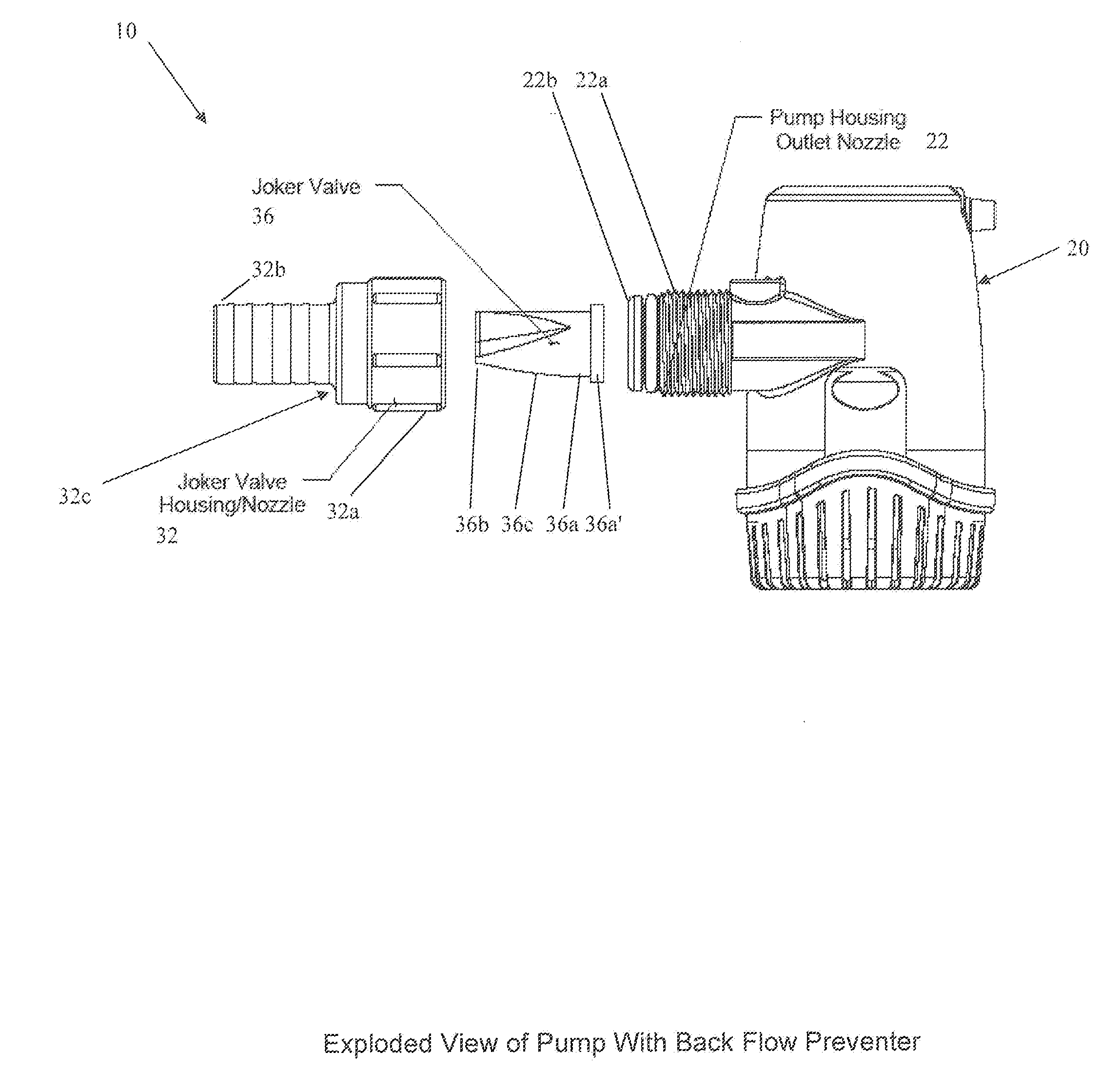
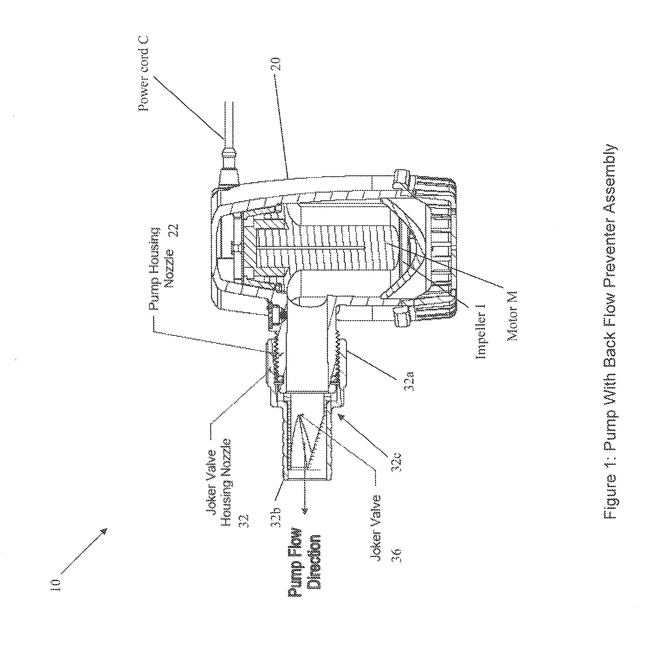
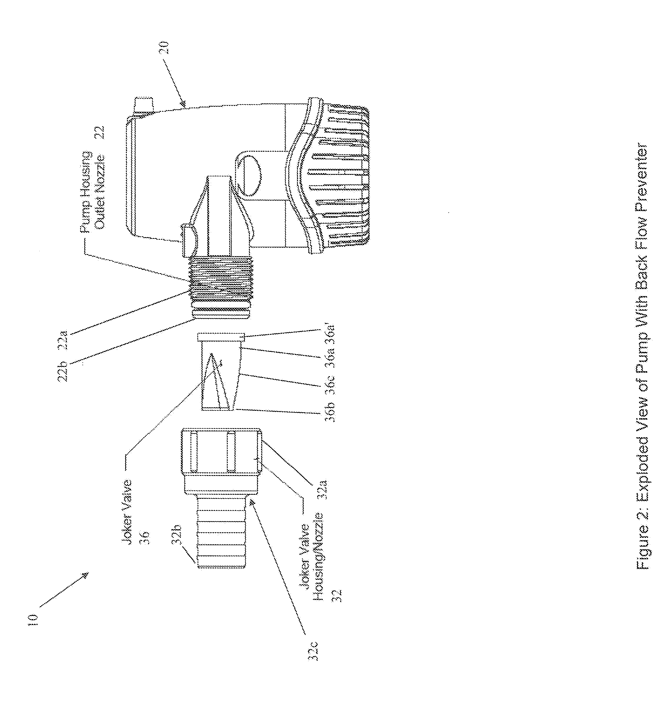
[0028]By way of example, FIGS. 1-2 show apparatus generally indicated as 10, e.g., for providing liquid from a reservoir of liquid contained in a vehicle, vessel or other equipment, featuring a pump 20 in combination with a back flow preventer assembly generally indicated as 30.

[0029]The pump 20 may be configured to respond to a level of liquid contained in the reservoir in the vehicle, vessel or other equipment, and turn on / off for pumping the liquid based on the level of the liquid sensed. The pump 20 may be configured with a pump housing outlet nozzle 22 for providing the liquid being pumped, consistent with that set forth below. By way of example, the pump 20 may take the form of a bilge pump to be arranged in the bilge of a vessel or boat for pumping water out of the bilge of the vessel or boat.

[0030]The back flow preventer assembly 30 includes a valve housing or nozzle 32 having an inlet 32a configured to couple to the pump housing outlet nozzle 22, having an outlet 32b config...


PUM


Abstract

Apparatus for providing liquid from a reservoir of liquid contained in a vehicle/vessel or other equipment, featuring a pump for pumping liquid having a pump housing outlet nozzle; and a back flow preventer assembly having an inlet end to couple to the outlet nozzle, having an outlet end to couple to an outlet hose for connecting to an outlet exiting a wall of a vehicle, vessel or other equipment, and having a duckbill-type check valve to provide liquid being pumped in one direction from the reservoir of the vehicle, vessel or other equipment to the outlet exiting the wall of the vehicle, vessel or other equipment via the outlet hose, and also configured to prevent residue liquid left in the outlet hose from flowing back into the pump and returning to the reservoir once the pump has completed pumping if the outlet exiting the wall of the vehicle, vessel or other equipment is above the outlet nozzle, so as to prevent on an on/off oscillation of the pump depending on the volume of residue liquid left in the outlet hose.

Description

[0001]By way of example, the present application is related to patent application Ser. No. 14 / 193,269 (911-17.31-1 / / M-RLE-X0007), filed on 28 Feb. 2014, which discloses a technique for solving an air lock problem, is assigned to the assignee of the present application, and is incorporated by reference in its entirety. See also related patent application Ser. No. 14 / 193,210 (911-17.30-1 / / M-RLE-X0006), filed on 28 Feb. 2014, which is assigned to the assignee of the present application, discloses a technique for solving the aforementioned air lock problem, and is incorporated by reference in its entirety. See also related patent application Ser. No. 13 / 917,970, (911-17.28-2 / / M-RLE-X0005), filed 14 Jun. 2013, which is assigned to the assignee of the present application, and is also incorporated by reference in its entirety.1BACKGROUND OF THE INVENTION[0002]1. Field of the Invention[0003]This invention relates to a pump; and more particularly, relates to a centrifugal pump, e.g., being u...

Claims


Application Information

Patent Timeline
IPC IPC(8): F04D15/02F16K15/14F04D1/04
CPCF04D15/0227F16K15/147F04D1/04F04D15/0022F04D29/4293
Inventor MOORMANN, RANDALL H.RAABE, TODD R.
Owner FLOW CONTROL LLC
Why Eureka
Try Eureka