Controllable electrical outlet with a controlled wired output

Active Publication Date: 2015-09-03
LUTRON TECH CO LLC
View PDF7 Cites 66 Cited by
  • Summary
  • Abstract
  • Description
  • Claims
  • Application Information

AI Technical Summary

Benefits of technology

[0008]As described herein, a load control system having a controllable electrical outlet may provide a low cost solution for controlling a plurality of standard electrical outlets. The load control system may not require any additional electrical devices (e.g., other than the controllable electrical outlet) to control the standard electrical outlets, which for example, may make it simple to install. The controllable electrical outlet may be coupled in series between a power source and at least one standard electrical outlet for controlling the power delivered to the standard electrical outlet. The controllable electrical outlet may comprise one or more of: (1) at least one electrical receptacle adapted to receive a plug of a plug-in electrical l

Problems solved by technology

In addition, consumers are becoming more sensitive to the amount of energy consumed by electrical loads, such as plug-in electrical loads that are plugged into electrical receptacles.
Such plug-in electrical loads may still consume energy to maintain a standby mode when “turned off” and are often referred to as “vampire” loads.
Installation of these prior art systems may be complicated since electrical wires need to be run from the remotely-located load control devices to the electrical outlets.
However, to program the load control device to be responsive to the input devices, the remotely-located load control devices must be accessed (e.g., to press a button on t

Method used


Image

  • Controllable electrical outlet with a controlled wired output
  • Controllable electrical outlet with a controlled wired output
  • Controllable electrical outlet with a controlled wired output

Examples


Example

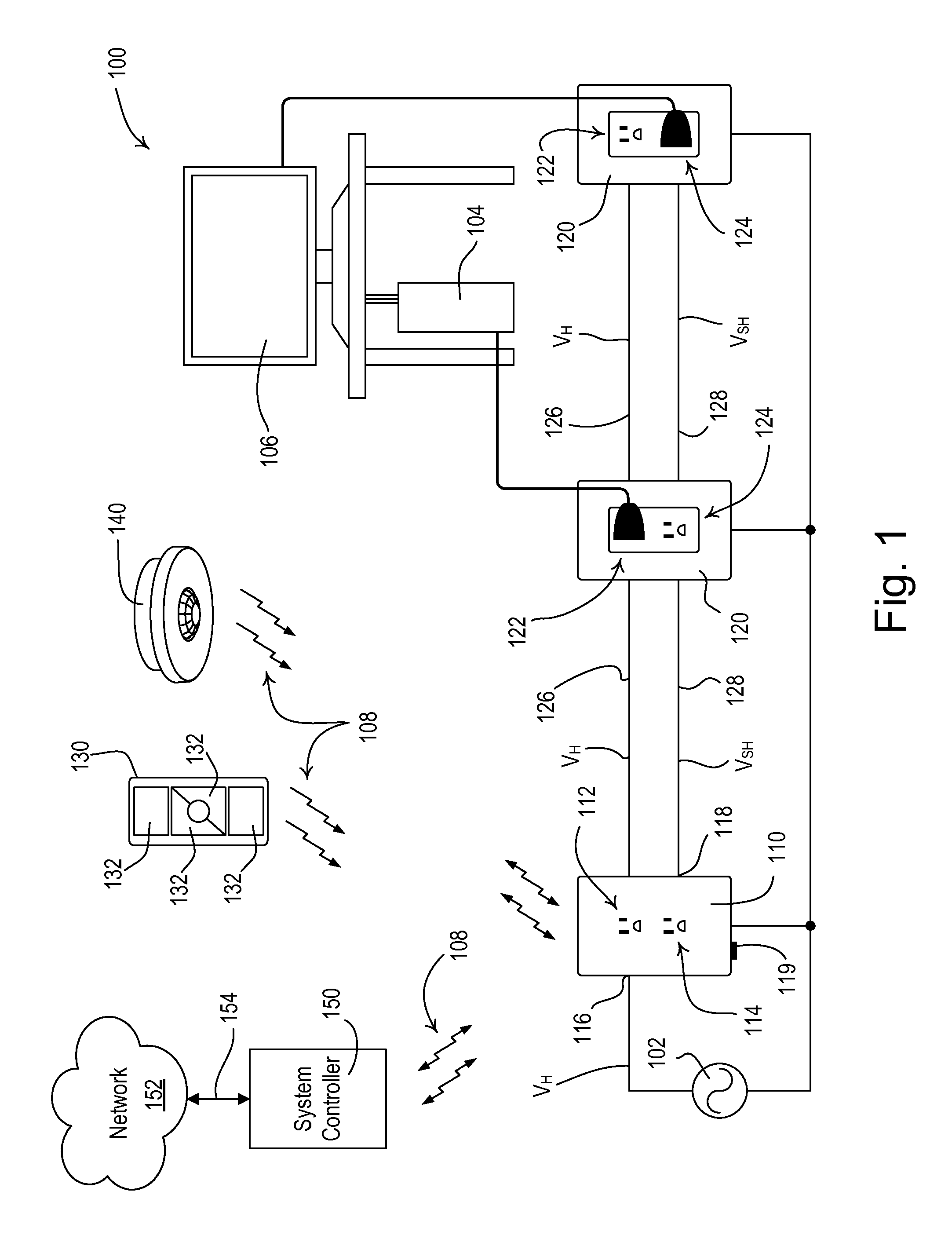
[0014]FIG. 1 is a simple diagram of an example load control system 100 having a load control device (e.g., a controllable electrical outlet 110), a plurality of standard electrical outlets 120, and a plurality of plug-in electrical loads (e.g., a computer 104 and a monitor 106). The controllable electrical outlet 110 may be adapted to be installed in a standard electrical wallbox (not shown). The controllable electrical outlet 110 may be adapted to be connected to a power source, such as an alternating-current (AC) power source 102 for receiving a hot voltage VH (e.g., an AC mains line voltage, such as 120 V at 60 Hz or 230 V at 50 Hz) at a line voltage input 116 (e.g., a hot terminal). The controllable electrical outlet 110 may also be connected to the neutral side of the AC power source 102. Alternatively or additionally, the controllable electrical outlet 110 may be configured to receive power from a direct-current (DC) power source.

[0015]The controllable electrical outlet 110 ma...


PUM


Abstract

A load control system having a controllable electrical outlet provides a low cost solution for controlling a plurality of standard electrical outlets. The controllable electrical outlet may be coupled in series between a power source and at least one standard electrical outlet for controlling the power delivered to the standard electrical outlet. The controllable electrical outlet may comprise an actuator for allowing the controllable electrical outlet to be associated with an input device for receiving digital messages from the input device. The controllable electrical outlet may be installed in a standard electrical wallbox, e.g., replacing a previously-installed standard electrical outlet. The actuator may be easily accessed to associate the controllable electrical outlet with the input device and a radio-frequency receiver and antenna may be located in the controllable electrical outlet to provide optimum reception of radio-frequency signals.

Description

CROSS-REFERENCE TO RELATED APPLICATIONS[0001]This application claims priority to commonly-assigned U.S. Provisional Application No. 61 / 946,127, filed Feb. 28, 2014, entitled CONTROLLABLE ELECTRICAL OUTLET WITH A CONTROLLED WIRED OUTPUT, the entire disclosure of which is hereby incorporated by reference.BACKGROUND[0002]1. Field of the Disclosure[0003]The present disclosure relates to a load control system for controlling the power delivered to one or more electrical loads, and more particularly, to a load control system comprising a controllable electrical outlet having a controlled wired output for controlling the power delivered to outlets of other electrical outlets and thus electrical loads connected to those outlets.[0004]2. Description of the Related Art[0005]Many consumers reduce the total cost of electrical energy by reducing the total energy usages of electrical loads, such as lighting loads. For example, lighting loads are often controlled in response to occupancy and vacan...

Claims


Application Information

Patent Timeline
IPC IPC(8): H02J3/00
CPCH02J3/005H01R13/6683H01R24/78H01R25/006H01R31/065H02J3/007H02J3/00
Inventor RANERI, DANIEL CURTISGUELLNITZ, JOSEPH C.SPIRA, JOEL S.
Owner LUTRON TECH CO LLC
Why Eureka
Try Eureka